Renault Koleos Service Repair Manual: B-pillar: General description
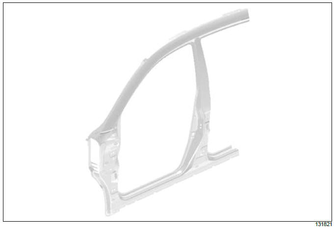
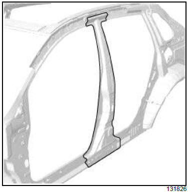
I - DESIGN OF THE STRUCTURAL COMPONENT
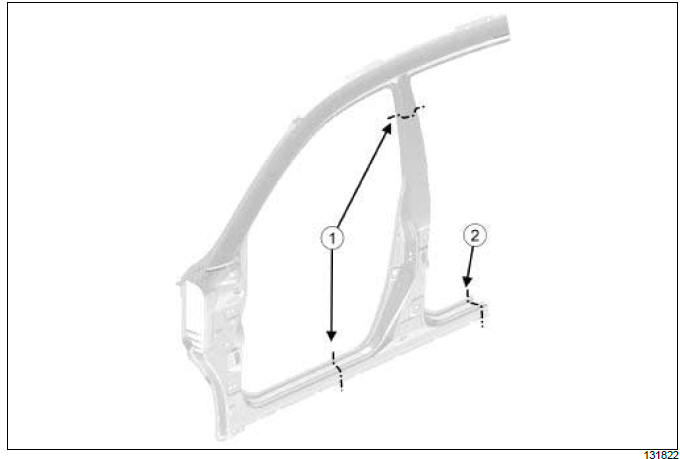
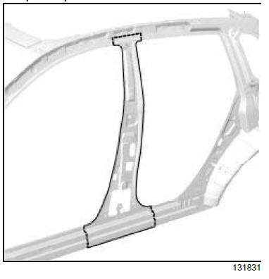
The B-pillar is obtained by extension from the front section body side. II - AREA TO BE CUT FOR PARTIAL REPLACEMENT
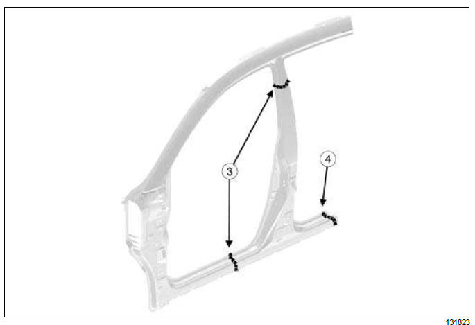
Cutting lines (1) and (2) show the area in which it is possible to carry out a partial replacement. Make the cutting line (2) on the butt weld. III - ASSEMBLY METHOD FOR A PARTIAL REPLACEMENT Only the connections which are specific to the partial replacement by cutting are indicated. If there are other issues regarding access to mating faces, the various replacement options are described in the basic instructions for structural bodywork repair (see MR 400, 40A, General Information).
Lines (3) and (4) on the diagram show a butt weld by continuous EGW welding. Weld (4) along the butt weld line.
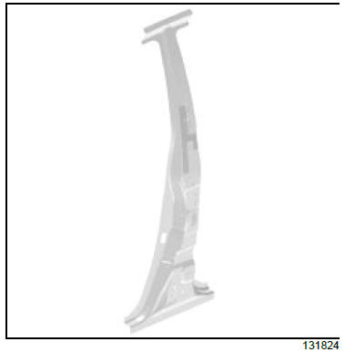
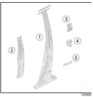
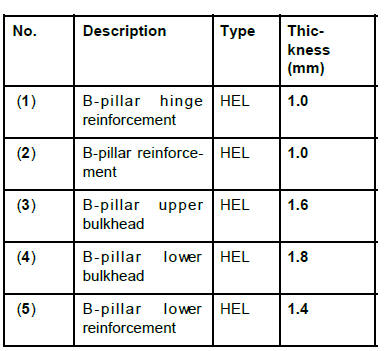
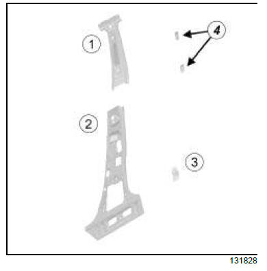
B-pillar reinforcement: Description
There is only one way of replacing this part:
I - COMPOSITION OF THE REPLACEMENT PART
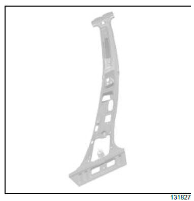
II - PART FITTED Complete replacement
For details of body side cuts (see 43A, Side upper structure, Body side front section: Description, page 43A-15) .
B-pillar lining: Description
The options for replacing this part are as follows:
I - COMPOSITION OF THE REPLACEMENT PART
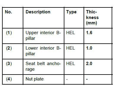
II - PART FITTED Partial replacement of the upper section
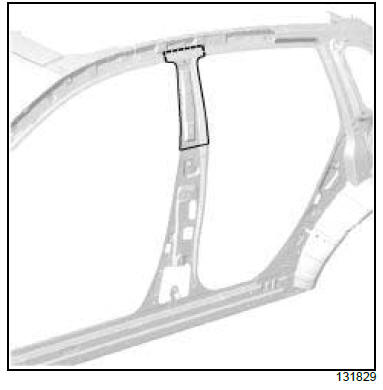
Partial replacement of the lower section
Complete replacement
|


See More:
Renault Koleos Owners Manual > Active emergency braking: System A
Operating principle Using the radar sensor, the system calculates the distance separating the vehicle from the one in front and alerts the driver if there is a risk of a front-end collision. The driver can then brake the vehicle to limit the damage arising from a collision. Note: make sure that the ...
Renault Koleos Owners Manual
- Getting to know your vehicle
- Driving
- Your comfort
- Maintenance
- Practical advice
- Technical specifications
Renault Koleos Service Repair Manual
