M9R
REMOVAL
I - REMOVAL PREPARATION OPERATION
- Position the vehicle on a two-post lift.
- Remove:
- the engine cover,
- the engine undertray,
- the clips from the air inlet sleeve,
- the air intake sleeve on the air filter unit,
- the battery,
- the battery tray,
- the air filter unit.
- Loosen the air filter unit air outlet duct clip on the turbocharger.
- Disconnect:
- the oil vapour rebreathing pipe from the oil separator,
- the air filter unit air outlet duct from the turbocharger.
- Fit a blanking plug in the opening of the oil separator.
- Remove:
- the windscreen wiper arms,
- the scuttle half-grille,
- the windscreen wiper mechanism,
- the scoop under the scuttle panel grille.
- Drain the engine cooling circuit .
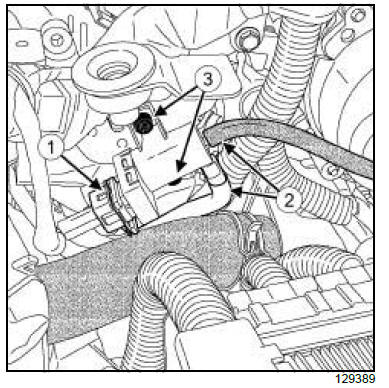
- Disconnect:
- the connector (1) from the EGR bypass solenoid
valve,
- the vacuum hoses (2) from the EGR bypass solenoid
valve.
- Remove:
- the EGR bypass solenoid valve bolts (3) ,
- the EGR bypass solenoid valve,
- the coolant outlet unit.
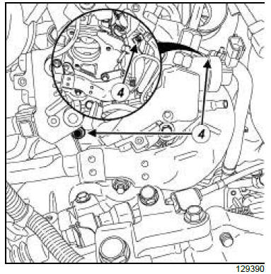
- Remove:
- the bolts (4) from the exhaust gas recirculation rigid
pipe heat shield on the exhaust manifold and on
the cylinder head,
- the heat shield from the exhaust gas recirculation
solenoid valve.
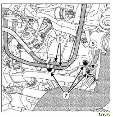
- Unclip:
- the fuel pipes (5) ,
- the electrical wiring (6) .
- Remove the bolts (7) from the intercooler water inlet
pipe.
- Move the intercooler water inlet pipe to one side.
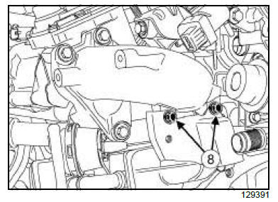
- Remove:
- the bolts (8) of the exhaust gas cooler coolant inlet
pipe support from the intake distributor,
- the exhaust gas cooler coolant inlet pipe support.
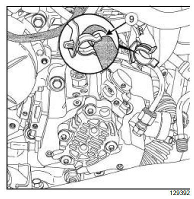
- Unclip the cooling hose (9) from the turbocharger.
- Remove:
- the exhaust gas recirculation rigid pipe between
the exhaust manifold and the exhaust gas cooler
- the catalytic converter
- the turbocharger
II - OPERATION FOR REMOVAL OF PART
CONCERNED
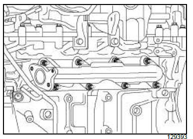
- Remove:
- the nuts and spacers from the exhaust manifold,
- the exhaust manifold,
- the exhaust manifold gasket.
REFITTING
I - REFITTING PREPARATION OPERATION
| WARNING
The joint faces must be clean, dry and free from
grease (avoid finger marks). |
- Always replace:
- the exhaust manifold studs, if they have been loosened
during the removal operation,
- the exhaust manifold nuts,
- the exhaust manifold gasket.
- Clean and degrease the bearing faces:
- of the exhaust manifold, if it is to be reused,
- of the cylinder head,
- of the exhaust gas recirculation rigid pipe heat
shield.
- Check if the exhaust manifold studs are torque tightened
to 9 N.m. Otherwise replace the exhaust manifold
studs which are loosened.
- Torque tighten the exhaust manifold studs (9 N.m)
using a roller-type stud removal tool.
II - REFITTING OPERATION FOR PART
CONCERNED
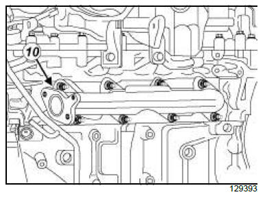
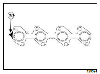
| Note:
Check if the manifold seal is correctly positioned.
The tab must be positioned at (10) . |
- Refit:
- the new exhaust manifold gasket,
- the exhaust manifold,
- the spacers.
- Finger tighten the new exhaust manifold nuts until
they are in contact.
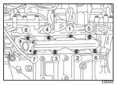
- Pretighten to torque and in order the exhaust manifold
nuts (18 N.m).
- Torque tighten in order the exhaust manifold nuts
(30 N.m).
III - FINAL OPERATION
- Refit:
- the turbocharger
- the catalytic converter
- the exhaust gas recirculation rigid pipe between
the exhaust manifold and the exhaust gas cooler
- Clip the cooling hose (9) onto the turbocharger.
- Fit the exhaust gas cooler coolant inlet pipe support
onto the intake distributor.
- Refit the exhaust gas cooler coolant inlet pipe support
bolts.
- Torque tighten the exhaust gas cooler coolant inlet
pipe support bolts (10 N.m).
- Position the intercooler water inlet pipe.
- Refit the intercooler water inlet pipe bolts.
- Torque tighten the intercooler water inlet pipe
bolts (10 N.m).
- Clip:
- the electrical wiring (6) ,
- the fuel pipes (5) .
- Position the heat shield for the exhaust gas recirculation
rigid pipe.
- Refit the EGR rigid pipe heat shield bolts
- Torque tighten the exhaust gas recirculation rigid
pipe heat shield bolts (10 N.m).
- Refit:
- the coolant outlet unit
- the water chamber hoses and pipes
- Fit the EGR bypass solenoid valve.
- Refit the EGR bypass solenoid valve bolts.
- Torque tighten the EGR bypass solenoid valve
bolts (10 N.m).
- Connect:
- the vacuum hoses on the EGR bypass solenoid
valve and on the exhaust gas cooler,
- the EGR bypass solenoid valve connector.
- Remove:
- the scoop under the scuttle panel grille
- the windscreen wiper mechanism
- the scuttle half-grille
- the windscreen wiper arms
- the air filter unit
- Connect the air filter unit air outlet duct to the turbocharger
and to the air filter unit.
- Torque tighten the air filter unit air outlet pipe
clips (5 N.m) using the tool (Mot. 1608).
- Remove the blanking plug from the opening of the oil
separator.
- Connect the oil vapour rebreathing pipe to the oil decanter.
- Refit:
- the battery tray
- the battery
- the air intake sleeve on the air filter unit.
- the clips of the air inlet sleeve.
- Fill the engine cooling system .
- Bleed the engine cooling system.
- Refit:
- the engine undertray,
- the engine cover.
2TR
REMOVAL
I - REMOVAL PREPARATION OPERATION
- Position the vehicle on a two-post lift.
- Disconnect the battery.
- Remove the engine undertray.
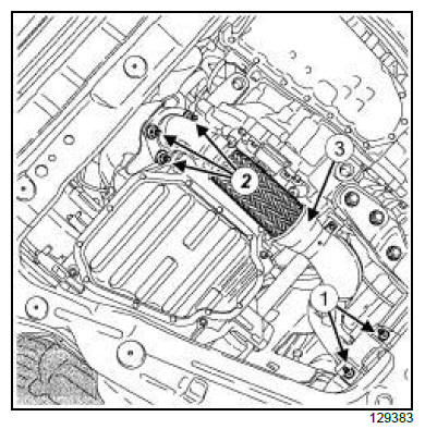
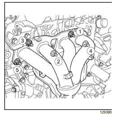
- Remove:
- the exhaust connecting pipe rubber mounting bush
support nuts (1) ,
- the exhaust connecting pipe nuts (2) ,
- the connector pipe (3) ,
- the seal,
- the front right-hand wheel,
- the front wheel arch liner.
- Disconnect the oxygen sensor connectors .
| Note:
Do not damage the oxygen sensor.
If the oxygen sensor falls on hard ground, for
example concrete, replace the sensor. |
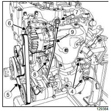
- Remove:
- the oxygen sensors (4)
- the accessories belt (5)
- the windscreen washer bottle neck
- the alternator (6)
- the dipstick (7)
- the dipstick guide tube bolt (8)
- the dipstick guide tube (9)
- the O-ring.
| Note:
The engine must remain covered to prevent
impurities from entering inside. |
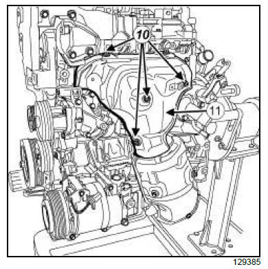
- Remove:
- the bolts (10) from the exhaust manifold upper heat
shield,
- the upper heat shield (11) from the exhaust manifold.
II - OPERATION FOR REMOVAL OF PART
CONCERNED
| Note:
The engine must remain covered to prevent
impurities from entering inside. |
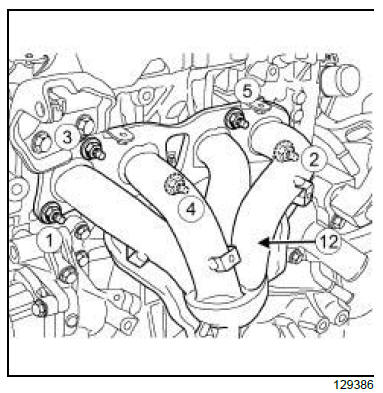
- Remove:
- the exhaust manifold nuts in order,
- the exhaust manifold (12) .
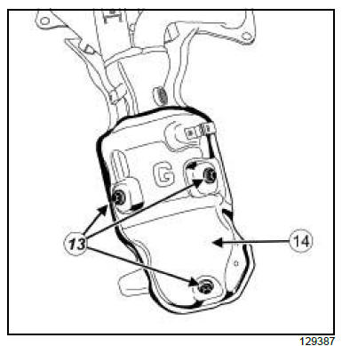
- Remove:
- the bolts (13) from the exhaust manifold lower heat
shield,
- the lower heat shield (14) from the exhaust manifold.
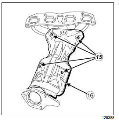
- Remove:
- the bolts (15) from the catalytic pre-converter heat
shield,
- the catalytic pre-converter heat shield (16) .
REFITTING
I - REFITTING PREPARATION OPERATION
II - REFITTING OPERATION FOR PART
CONCERNED
- Refit:
- the catalytic pre-converter heat shield,
- the catalytic pre-converter heat shield bolts.
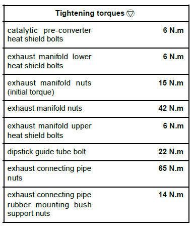
- Torque tighten the catalytic pre-converter heat
shield bolts (6 N.m).
- Refit:
- the exhaust manifold lower heat shield,
- the exhaust manifold lower heat shield bolts.
- Torque tighten the exhaust manifold lower heat
shield bolts (6 N.m).
- Refit:
- the new exhaust manifold gasket,
- the exhaust manifold,
- the exhaust manifold nuts.
- Torque tighten in order:
- the exhaust manifold nuts (initial torque) (15
N.m),
- the exhaust manifold nuts (42 N.m).
III - FINAL OPERATION
- Refit:
- the exhaust manifold upper heat shield,
- the exhaust manifold upper heat shield bolts.
- Torque tighten the exhaust manifold upper heat
shield bolts (6 N.m).
- Refit:
- the new O-ring,
- the dipstick guide tube,
- the dipstick guide tube bolt,
- the dipstick.
- Torque tighten the dipstick guide tube bolt (22
N.m).
- Refit:
- the alternator
- the windscreen washer bottle neck
- the accessories belt
- the oxygen sensors
- Connect the oxygen sensor connectors.
- Refit:
- the front wheel arch liner
- the front right-hand wheel
- the new seal
- the connector pipe
- the exhaust connecting pipe nuts
- the exhaust connecting pipe rubber mounting bush
support nuts.
- Torque tighten:
- the exhaust connecting pipe nuts (65 N.m),
- the exhaust connecting pipe rubber mounting
bush support nuts (14 N.m).
- Refit the engine undertray.
- Connect the battery.
|


