M9R
REMOVAL
I - REMOVAL PREPARATION OPERATION
- Position the vehicle on a two-post lift.
- Remove:
- the engine cover,
- the engine undertray.
- Drain the engine cooling circuit.
- Remove:
- the clips from the air inlet sleeve,
- the air intake sleeve on the air filter unit,
- the battery,
- the battery tray.
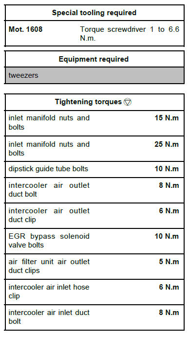
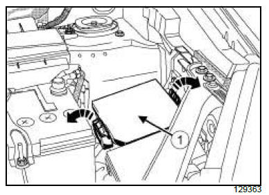
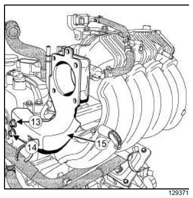
- Turn the clip (1) on the intercooler air inlet duct.
- Remove the intercooler air inlet duct bolt (2) from the
fuel pipe support.
- Loosen the clip (3) on the intercooler air inlet duct.
- Remove:
- the air inlet duct assembly (4) from the intercooler,
- the air filter unit.
- Loosen the air filter unit air outlet duct clip on the turbocharger.
- Disconnect:
- the oil vapour rebreathing pipe from the oil separator,
- the air filter unit air outlet duct from the turbocharger.
- Fit a blanking plug in the opening of the oil separator.
- Remove:
- the windscreen wiper arms
- the scuttle half-grille
- the windscreen wiper mechanism
- the scoop under the scuttle panel grille
- the water chamber
- the exhaust gas recirculation rigid pipe between
the exhaust manifold and the exhaust gas cooler.
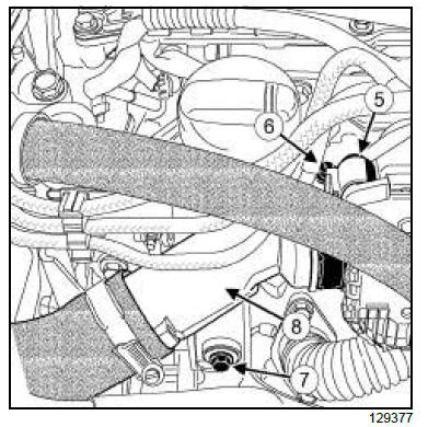
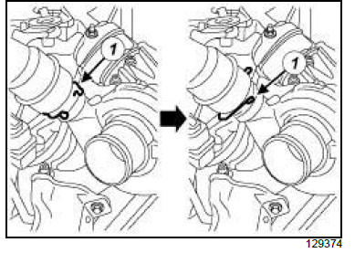
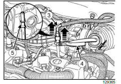
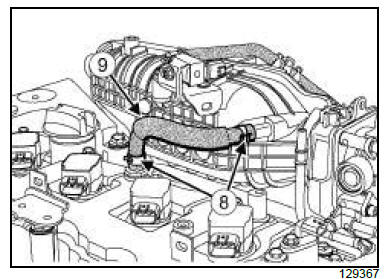
- Disconnect the connector from the damper valve
wiring (5) .
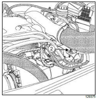
- Loosen the clip (6) on the intercooler air inlet duct.
- Remove the bolt (7) from the intercooler air outlet
duct.
- Disconnect the intercooler air outlet duct (8) from the
damper valve.
- Move the intercooler air outlet duct to one side.
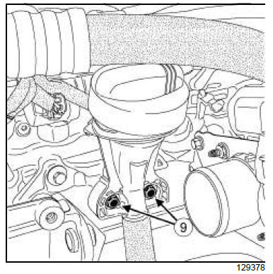
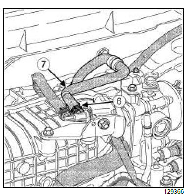
- Remove:
- the dipstick guide tube bolts (9) ,
- the dipstick guide tube.
- Plug the opening of the dipstick guide tube on the
cylinder block.
- Remove the damper valve.
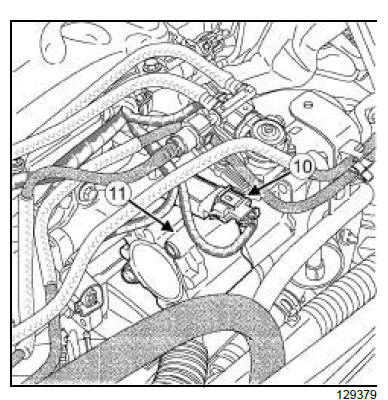
- Disconnect the connector (10) from the turbocharger
pressure sensor.
- Remove:
- the turbocharger pressure sensor housing (11) ,
- the exhaust gas recirculation rigid pipe between
the exhaust gas recirculation solenoid valve and
the exhaust gas cooler,
- the EGR solenoid valve,
- the starter ,
- the intercooler,
- the front right-hand wheel,
- the front right-hand wheel arch liner,
- the accessories belt,
- the alternator,
- the multifunction support.
II - OPERATION FOR REMOVAL OF PART
CONCERNED
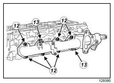
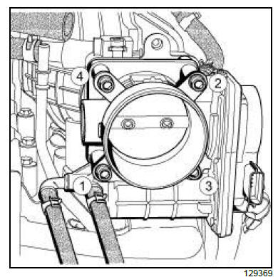
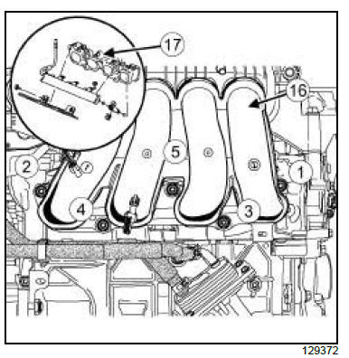
- Remove:
- the intake distributor bolts (12) ,
- the intake distributor nuts (13) ,
- the inlet manifold,
- the inlet manifold gasket.
REFITTING
I - REFITTING PREPARATION OPERATION
| WARNING
The joint faces must be clean, dry and free from
grease (avoid finger marks). |
- Clean:
- the cylinder head joint face,
- the intake distributor joint face,
- the exhaust gas recirculation rigid pipe joint faces,
- the turbocharger pressure sensor housing joint faces,
- the damper valve seal face.
- Always replace:
- the inlet manifold gasket,
- the exhaust gas recirculation rigid pipe between
the exhaust manifold and the exhaust gas cooler,
- the exhaust gas recirculation rigid pipe seal on the
exhaust manifold,
- the exhaust gas recirculation rigid pipe seals,
- the exhaust gas recirculation rigid pipe clip,
- the rigid exhaust gas recirculation pipe bolts,
- the coolant outlet unit seal,
- the gasket between the intake distributor and the
EGR solenoid valve.
- the seal between the turbocharger pressure sensor
housing and the EGR solenoid valve,
- the seal between the damper valve and the turbocharger
pressure sensor housing,
- the intercooler air inlet duct seal.
II - REFITTING OPERATION FOR PART
CONCERNED
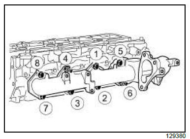
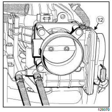
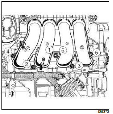
- Refit:
- the new intake distributor seal,
- the inlet manifold,
- the inlet manifold nuts and bolts.
- Pretighten to torque and in order the inlet manifold
nuts and bolts (15 N.m).
- Torque tighten in order the inlet manifold nuts and
bolts (25 N.m).
III - FINAL OPERATION.
- Refit:
- the multifunction support
- the alternator
- the accessories belt
- the front right-hand wheel arch liner
- the front right-hand wheel
- the intercooler
- the starter
- the new seal between the EGR solenoid valve and
the intake distributor
- the EGR solenoid valve
- the new exhaust gas recirculation rigid pipe seals
- the exhaust gas recirculation rigid pipe between
the exhaust gas recirculation solenoid valve and
the exhaust gas cooler
- the new seal between the turbocharger pressure
sensor housing and the EGR solenoid valve
- the turbocharger pressure sensor housing.
- Connect the turbocharger pressure sensor connector.
- Refit:
- the seal between the damper valve and the turbocharger
pressure sensor housing,
- the damper valve.
- Remove the plug from the opening of the dipstick
guide tube on the cylinder block.
- Torque tighten the dipstick guide tube bolts (10
N.m).
- Connect the intercooler air outlet duct to the damper
valve.
- Refit the intercooler air outlet duct bolt.
- Torque tighten:
- the intercooler air outlet duct bolt (8 N.m),
- the intercooler air outlet duct clip (6 N.m) using
the tool (Mot. 1608).
- Connect the damper valve wiring connector.
- Refit:
- the exhaust gas recirculation rigid pipe seal on the
exhaust manifold
- the exhaust gas recirculation rigid pipe between
the exhaust manifold and the exhaust gas cooler
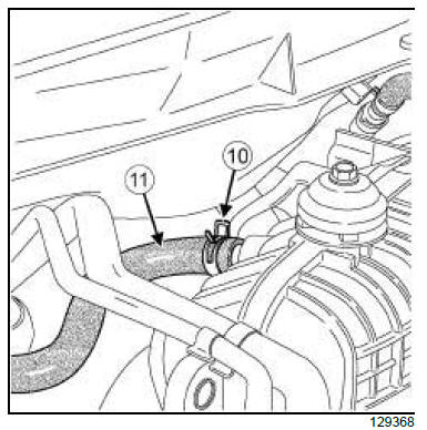
- the coolant outlet unit seal
- the water chamber
- the water chamber hoses and pipes
- Fit the EGR bypass solenoid valve.
- Refit the EGR bypass solenoid valve bolts.
- Torque tighten the EGR bypass solenoid valve
bolts (10 N.m).
- Connect:
- the vacuum hoses on the EGR bypass solenoid
valve and on the exhaust gas cooler,
- the EGR bypass solenoid valve connector.
- Refit the air filter unit.
- Connect the air filter unit air outlet duct to the turbocharger
and to the air filter unit.
- Torque tighten the air filter unit air outlet duct
clips (5 N.m) using the tool (Mot. 1608).
- Remove the blanking plug from the opening of the oil
separator.
- Connect the oil vapour rebreathing hose to the oil
separator.
- Fit the intercooler air inlet duct assembly onto the intercooler
air inlet pipe.
- Torque tighten the intercooler air inlet hose clip (6
N.m) using the tool (Mot. 1608).
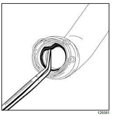
- Remove the intercooler air inlet duct seal using a
tweezers.
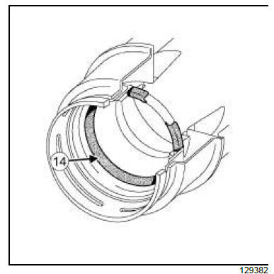
| Note:
Check whether the intercooler air inlet duct seal
(14) is correctly positioned. |
- Refit the new intercooler air inlet duct seal.
- Turn the intercooler air inlet duct to fit the clip in its
housing.
- Clip the intercooler air inlet duct onto the turbocharger.
- Refit the intercooler air inlet duct bolt to the fuel pipe
support.
- Torque tighten the intercooler air inlet duct bolt (8
N.m).
- Refit:
- the battery tray
- the battery
- the scoop under the scuttle panel grille
- the windscreen wiper mechanism
- the scuttle half-grille
- the windscreen wiper arms
- the air intake sleeve on the air filter unit
- the clips of the air inlet sleeve.
- Fill the engine cooling system .
- Bleed the engine cooling system .
- Refit:
- the engine undertray,
- the engine cover.
2TR
| IMPORTANT
Wear protective gloves during the operation. |
REMOVAL
I - REMOVAL PREPARATION OPERATION
- Position the vehicle on a two-post lift.
| IMPORTANT
To prevent the vehicle from falling, lash it to the
vehicle lift using a strap. |
- Remove the engine cover.
- Remove the air inlet sleeve.
- Disconnect the cover (1) from the Protection and
Switching Unit.
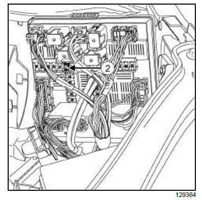
- Remove the fuse (2) of the fuel pump(F13) (15A).
- Release the fuel pressure in the fuel pipe after starting
the engine.
| Note:
After switching the engine off, start it again two or
three times to fully relieve the fuel pressure. |
- Remove:
- the battery
- the battery tray
- the air filter unit
- the engine cover
- the air resonator located on the rocker cover
- the air inlet duct.
- Remove the plug of the fuel supply union.
IMPORTANT
During this operation, be sure to:
- refrain from smoking or bringing red hot objects
close to the working area,
- be careful of fuel splashes when disconnecting
the union.
|
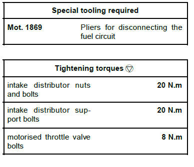
- Disconnect the quick-release union (3) using the tool
(Mot. 1869) (4) as illustrated.
| Note:
Insert the tool (Mot. 1869) (4) into the second
retaining part (5) . |
- Remove the petrol vapour rebreathing pipe clip (6) .
- Disconnect the petrol vapour rebreathing pipe (7) .
- Remove the clips (8) of the oil vapour rebreathing
hose.
- Disconnect the oil vapour rebreathing hose (9) .
- Remove the clip (10) from the vacuum pipe of the
brake servo.
- Disconnect the vacuum pipe (11) from the brake servo.
- Remove:
- the windscreen wiper arms
- the scuttle panel half-grille
- the windscreen wiper mechanism
- the scoop under the scuttle panel grille.
- Disconnect the motorised throttle valve connector.
- Remove:
- in order the motorised throttle valve bolts,
- the motorised throttle valve without disconnecting
the coolant pipes.
- Move aside the throttle valve (12) .
- Remove:
- the intake distributor support bolts (13) and (14) ,
- the intake distributor support (15) ,
- the seal.
II - OPERATION FOR REMOVAL OF PART
CONCERNED
- Remove:
- in order, the intake distributor bolts and nuts,
- the inlet manifold (16) ,
- the intake distributor seal,
- the intake distributor adapter (17) ,
- the intake distributor adapter seal.
| Note:
The engine must remain covered to prevent
impurities from entering inside. |
REFITTING
I - REFITTING PREPARATION OPERATION
- Always replace:
- the intake distributor seal,
- the intake distributor adapter seal,
- the motorised throttle valve seal.
II - REFITTING OPERATION FOR PART
CONCERNED
- Refit:
- the new intake distributor adapter seal,
- the intake distributor adapter,
- the new intake distributor seal,
- the inlet manifold,
- the intake distributor nuts and bolts.
- Torque tighten in order the intake distributor nuts
and bolts (20 N.m).
| Note:
Mark (6) indicates retightening of the bolt to a
torque of 20 N.m. |
III - FINAL OPERATION
- Refit:
- the new intake distributor support seal,
- the intake distributor support,
- the intake distributor support bolts.
- Torque tighten the intake distributor support bolts
(20 N.m).
- Refit:
- the new motorised throttle valve seal,
- the motorised throttle valve bolts.
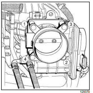
- Torque tighten in order the motorised throttle
valve bolts (8 N.m).
- Connect the motorised throttle valve connector.
- Refit:
- the scoop under the scuttle panel grille
- the windscreen wiper mechanism
- the scuttle panel half-grille
- the windscreen wiper arms.
- Connect the brake servo vacuum pipe.
- Refit the clip of the vacuum pipe of the brake servo.
- Connect the oil vapour rebreathing hoses.
- Refit the clips of the oil vapour rebreathing hose.
- Disconnect the petrol vapour rebreathing pipe.
- Refit the petrol vapour rebreathing pipe clip.
- Connect the quick-release union of the fuel supply.
| Note:
Check the condition of the quick-release union
connection again. |
- Remove the fuel supply union plug.
- Refit:
- the air inlet duct
- the air resonator located on the rocker cover
- the engine cover
- the air filter unit
- the battery tray
- the battery
- the fuel pump fuse
- the Protection and Switching Unit cover.
- Refit the air intake sleeve.
|


