LEFT-HAND DRIVE
REMOVAL
I - REMOVAL PREPARATION OPERATION
- Remove:
- the dashboard lower cover on the driver's side (see
Dashboard: Removal - Refitting) (57A, Interior
equipment),
- the A-pillar air distribution duct (see Front footwell
air distribution duct: Removal - Refitting) (61A,
Heating system),
- the left-hand trim on the centre panel (see Centre
front panel: Removal - Refitting) (57A, Interior
equipment).
II - OPERATION FOR REMOVAL OF PART
CONCERNED
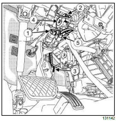
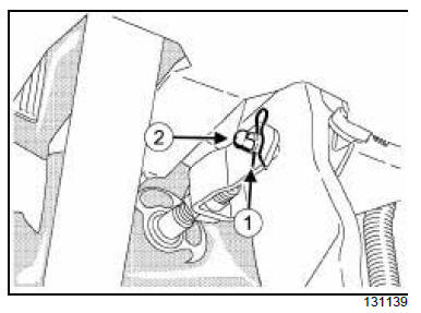
- Remove:
- the connector (5) from the brake light switch,
- the connector (2) from the mode flap motor,
- the connector (3) from the accelerator pedal position
sensor.
- Remove the mode flap motor (4) .
CRUISE CONTROL
- Disconnect the connector (1) from the brake switch.
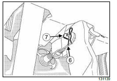
- Remove:
- the brake pedal circlip (6) ,
- the connector shaft (7) between the brake pedal
and the brake servo pushrod.
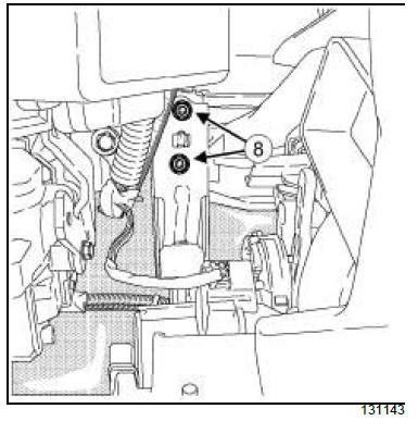
- Remove:
- the brake pedal protector bolts (8) ,
- the brake pedal protector.
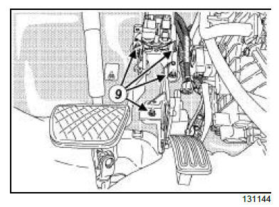
- Remove:
- the nuts (9) from the brake - accelerator pedal assembly,
- the brake - accelerator pedal assembly,
- the brake pedal switch from the brake-accelerator
pedal assembly (see 37A, Mechanical component
controls, Brake pedal switch: Removal -
Refitting, page 37A-34) .
REFITTING
I - REFITTING PREPARATION OPERATION
- Check the condition of the connecting shaft and replace
it if it is damaged.
II - REFITTING OPERATION FOR PART
CONCERNED
- Refit:
- the brake pedal switch on the brake-accelerator
pedal assembly (see 37A, Mechanical component
controls, Brake pedal switch: Removal -
Refitting, page 37A-34) ,
- the brake - accelerator pedal assembly,
- the nuts on the brake-accelerator pedal assembly.
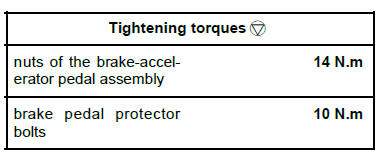
- Torque tighten the nuts of the brake-accelerator
pedal assembly (14 N.m).
- Refit:
- the brake pedal protector,
- the brake pedal protector bolts.
- Torque tighten the brake pedal protector bolts (10
N.m).
| IMPORTANT
To avoid breaking the connection between the
brake servo pushrod and the brake pedal, check
that the safety clevis pin is locked onto the brake
servo pushrod by tilting it from the top downwards. |
- Refit:
- the connecting shaft between the brake pedal and
the brake servo pushrod,
- the brake pedal circlip,
- the mode flap motor.
- Connect:
- the connector on the accelerator pedal position
sensor,
- the connector on the mode flap motor,
- the brake light switch connector.
CRUISE CONTROL
- Connect the brake switch connector.
III - FINAL OPERATION
- Refit:
- the left-hand trim on the centre panel (see Centre
front panel: Removal - Refitting) (57A, Interior
equipment),
- the A-pillar air distribution duct (see Front footwell
air distribution duct: Removal - Refitting) (61A,
Heating system),
- the lower cover of the dashboard on the driver's
side (see Dashboard: Removal - Refitting) (57A,
Interior equipment).
RIGHT-HAND DRIVE
REMOVAL
I - REMOVAL PREPARATION OPERATION
- Position the vehicle on a two-post lift (see Vehicle:
Towing and lifting) (02A, Lifting equipment).
| IMPORTANT
To avoid any risk of triggering when working on
or near a pyrotechnic component (airbags or pretensioners),
lock the airbag computer using the
diagnostic tool.
When this function is activated, all the trigger
lines are inhibited and the airbag warning light on
the instrument panel lights up continuously (ignition
on). |
- Disconnect the battery (see Battery: Removal - Refitting)
(80A, Battery).
- Remove:
- the dashboard (see Dashboard: Removal - Refitting)
(57A, Interior equipment).
- the dashboard cross member (see Dashboard
cross member: Removal - Refitting) (42A, Upper
front structure).
II - OPERATION FOR REMOVAL OF PART
CONCERNED
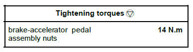
- Remove:
- the brake pedal circlip (1) ,
- the connector shaft (2) between the brake pedal
and the brake servo pushrod.
- Disconnect:
- the connector (3) from the brake light switch,
- the position sensor connector (4) from the accelerator
pedal.
CRUISE CONTROL
- Disconnect the brake switch connector (5) .
- Remove the brake pedal switch from the brake-accelerator
pedal assembly (see 37A, Mechanical
component controls, Brake pedal switch: Removal
- Refitting, page 37A-34) .
- Unclip the electrical wiring from the brake-accelerator
pedal assembly.
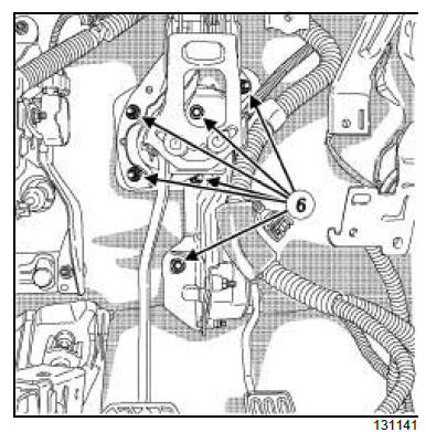
- Remove:
- the nuts (6) from the brake-accelerator pedal assembly,
- the brake-accelerator pedal assembly.
REFITTING
I - REFITTING PREPARATION OPERATION
- Check the condition of the connecting shaft and replace
it if it is damaged.
II - REFITTING OPERATION FOR PART
CONCERNED
- Refit:
- the brake-accelerator pedal assembly,
- the nuts on the brake-accelerator pedal assembly.
- Torque tighten the brake-accelerator pedal assembly
nuts (14 N.m).
- Refit the brake pedal switch on the brake-accelerator
pedal assembly (see 37A, Mechanical component
controls, Brake pedal switch: Removal -
Refitting, page 37A-34)
- Connect:
- the brake light switch connector,
- the accelerator position sensor connector.
CRUISE CONTROL
- Connect the brake switch connector.
- Clip the electrical wiring on the brake-accelerator
pedal assembly.
| IMPORTANT
To avoid breaking the connection between the
brake servo pushrod and the brake pedal, check
that the safety clevis pin is locked onto the brake
servo pushrod by tilting it from the top downwards. |
- Refit:
- the connecting shaft between the brake pedal and
the brake servo pushrod,
- the brake pedal circlip,
III - FINAL OPERATION.
- Refit:
- the dashboard cross member (see Dashboard
cross member: Removal - Refitting) (42A, Upper
front structure).
- the dashboard (see Dashboard: Removal - Refitting)
(57A, Interior equipment).
|


