LEFT-HAND DRIVE
| WARNING
Prepare for the flow of fluid, and protect the surrounding
components. |
REMOVAL
I - REMOVAL PREPARATION OPERATION
- Position the vehicle on a two-post lift (see Vehicle:
Towing and lifting) (02A, Lifting equipment).
M9R
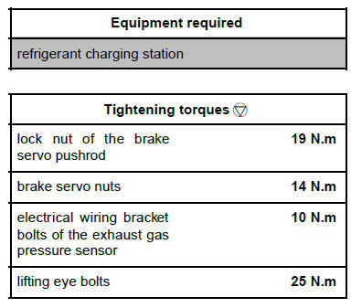
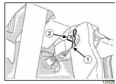
- Disconnect the turbocharging pressure regulation
solenoid valve connector (1) .
- Unclip:
- the turbocharging pressure regulation solenoid
valve from its support (2) ,
- the hoses of the turbocharging pressure regulation
solenoid valve at (3) from the battery tray.
- Remove:
- the battery (see Battery: Removal - Refitting)
(80A, Battery),
- the battery tray (see Battery tray: Removal - Refitting)
(80A, Battery),
- the air filter box (see Air filter unit: Removal - Refitting)
(12A, Fuel mixture),
- the air filter box air outlet pipe,
- the brake master cylinder (see 37A, Mechanical
component controls, Master cylinder: Removal
- Refitting, page 37A-1) .
II - OPERATION FOR REMOVAL OF PART
CONCERNED
- Disconnect the hose (5) from the brake servo.
- Remove:
- the brake pedal circlip (6) ,
- the connector shaft (7) between the brake pedal
and the brake servo pushrod.
- Remove:
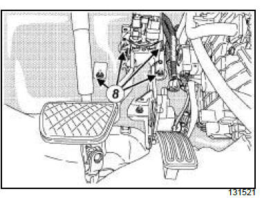
- the brake servo nuts (8) ,
- the brake servo.
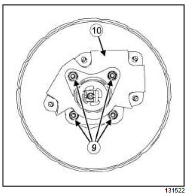
- Remove:
- the nuts (9) from the brake servo bracket,
- the bracket (10) from the brake servo.
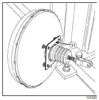
- Remove the seal (11) from the brake servo.
REFITTING
I - REFITTING PREPARATION OPERATION
- Always replace the brake servo seal.
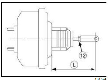
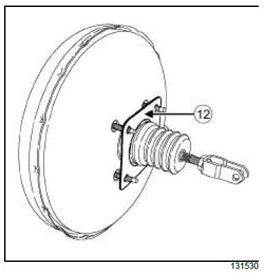
- Undo the lock nut (12) of the brake servo pushrod.
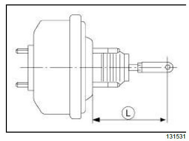
- Check that dimension L is between 150.7 and 157.7
mm.
- If dimension L is not correct, adjust the pushrod.
- Torque tighten the lock nut of the brake servo
pushrod (19 N.m)
II - REFITTING OPERATION FOR PART
CONCERNED
- Refit:
- the new seal of the brake servo,
- the brake servo bracket,
- the brake servo bracket nuts.
- Torque tighten the brake servo bracket nuts (14
N.m).
| IMPORTANT
To avoid breaking the connection between the
brake servo pushrod and the brake pedal, check
that the safety clevis pin is locked onto the brake
servo pushrod by tilting it from the top downwards. |
- Refit:
- the brake servo on the vehicle,
- the brake servo nuts (8) ,
- Torque tighten the brake servo nut (14 N.m).
- Refit:
- the connector shaft (7) between the brake pedal
and the brake servo pushrod,
- the brake pedal circlip (6) .
AIR CONDITIONING 01
- Connect the vacuum pipe on the brake servo.
III - FINAL OPERATION
- Refit:
- the brake master cylinder (see 37A, Mechanical
component controls, Master cylinder: Removal
- Refitting, page 37A-1) ,
- the air filter box air outlet pipe,
- the air filter box (see Air filter unit: Removal - Refitting)
(12A, Fuel mixture),
- the air filter box (see Air filter unit: Removal - Refitting)
(12A, Fuel mixture),
- the battery tray (see Battery tray: Removal - Refitting)
(80A, Battery).
M9R
- Clip:
- the hoses of the turbocharging pressure regulation
solenoid valve on the battery tray,
- the turbocharging pressure regulation solenoid
valve on its support.
- Connect the turbocharging pressure regulation solenoid
valve connector.
- Refit the battery (see Battery: Removal - Refitting)
(80A, Battery).
- Bleed the brake circuit (see 30A, General information,
Braking circuit: Bleed, page 30A-4) .
6-SPEED MANUAL GEARBOX
- Bleed the clutch circuit (see 37A, Mechanical component
controls, Clutch circuit: Bleed, page 37A-
48) .
M9R, and RIGHT-HAND DRIVE
| WARNING
Prepare for the flow of fluid, and protect the surrounding
components. |
REMOVAL
I - REMOVAL PREPARATION OPERATION
- Position the vehicle on a two-post lift (see Vehicle:
Towing and lifting) (02A, Lifting equipment).
- Drain the refrigerant fluid circuit using the refrigerant
charging station (see Refrigerant circuit:
Draining - Filling) (62A, Air conditioning).
- Disconnect the battery (see Battery: Removal - Refitting)
(80A, Battery).
- Remove:
- the engine cover,
- the windscreen wiper arms (see Windscreen wiper
arm: Removal - Refitting) (85A, Wiping -
Washing),
- the scuttle half-grille (see Scuttle panel grille: Removal
- Refitting) (56A, Exterior equipment),
- the windscreen wiper mechanism (see Windscreen
wiper mechanism: Removal - Refitting)
(85A, Wiping - Washing).
- the scoop under the scuttle panel grille (see Scoop
under the scuttle panel grille: Removal - Refitting)
(56A, Exterior equipment),
- the bulkhead insulation (see Bulkhead insulation:
Removal - Refitting) (68A, Soundproofing),
- the master cylinder (see 37A, Mechanical component
controls, Master cylinder: Removal - Refitting,
page 37A-1) (37A, Mechanical component
controls),
- the air inlet sleeve (see Air filter unit: Removal -
Refitting) (Fuel mixture),
- the air filter box (see Air filter unit: Removal - Refitting)
(Fuel mixture),
- the brake pipes between the hydraulic unit and the
master cylinder (see 31A, Front axle components,
Hydraulic unit - master cylinder brake
pipe: Removal - Refitting, page 31A-16) .
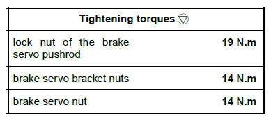
AIR CONDITIONING 01 or AIR CONDITIONING 02
- Remove the connecting pipe (1) (see Compressor
- condenser connecting pipe: Removal - Refitting)
.
- Remove:
- the heat shield from the turbocharger (see Turbocharger:
Removal - Refitting) (12B, Turbocharging),
- the oxygen sensor (see Oxygen sensor: Removal
- Refitting) (13B, Diesel injection).

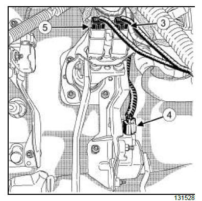
- Disconnect the exhaust gas pressure sensor connector
(2) .
- Remove:
- the pipe (3) of the exhaust gas pressure sensor
from the lifting eye (see Turbocharger: Removal -
Refitting) (12B, Turbocharging),
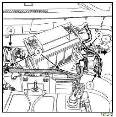
- the lifting eye (4) ,
- the bolt (5) from the wiring bracket.
- Move aside the electrical wiring with the bracket.
6-SPEED MANUAL GEARBOX
- Remove the clutch master cylinder (see 37A, Mechanical
component controls, Clutch master cylinder:
Removal - Refitting, page 37A-55) .
- Remove:
- the dashboard lower cover on the driver's side (see
Dashboard: Removal - Refitting) (57A, Interior
equipment),
- the A-pillar air distribution duct (see Front footwell
air distribution duct: Removal - Refitting) (61A,
Heating system).
II - OPERATION FOR REMOVAL OF PART
CONCERNED
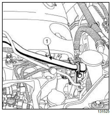
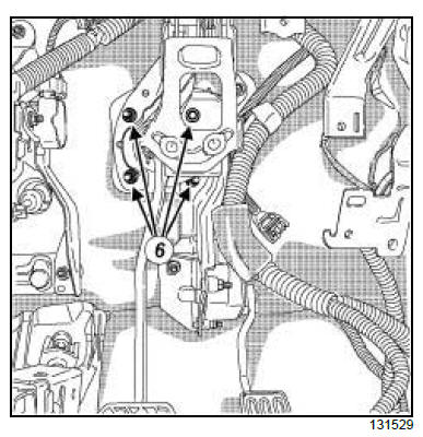
- Remove:
- the brake pedal circlip (6) ,
- the connector shaft (7) between the brake pedal
and the brake servo pushrod.
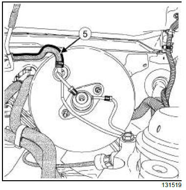
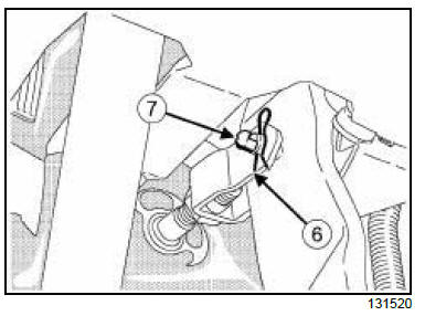
- Disconnect:
- the connector (8) from the brake light switch,
- the accelerator position sensor connector (9) .
AIR CONDITIONING 01
- Disconnect the connector (10) from the brake
switch.
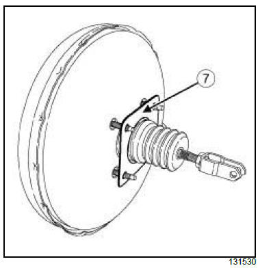
- Remove:
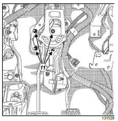
- the brake servo nuts (11) ,
- the brake servo.
- Remove the seal (12) from the brake servo.
REFITTING
I - REFITTING PREPARATION OPERATION
- Always replace the brake servo seal.
- Check the condition of the connecting shaft and replace
it if it is damaged.
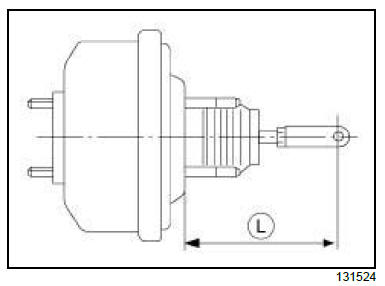
- Loosen the lock nut of the brake servo pushrod.
- Check that dimension L is between 150.7 and 157.7
mm.
- If dimension L is not correct, adjust the pushrod.
- Torque tighten the lock nut of the brake servo
pushrod (19 N.m).
II - REFITTING OPERATION FOR PART
CONCERNED
| Note:
This operation requires two people. |
- Refit:
- the brake servo with a new seal,
- the brake servo nuts.
- Torque tighten the brake servo nuts (14 N.m).
- Refit:
- the connecting shaft between the brake pedal and
the brake servo pushrod,
- the brake pedal circlip.
- Connect:
- the brake light switch connector,
- the accelerator position sensor connector.
AIR CONDITIONING 01
- Connect the brake switch connector.
III - FINAL OPERATION.
- Refit:
- the A-pillar air distribution duct (see Front footwell
air distribution duct: Removal - Refitting) (61A,
Heating system),
- the dashboard lower cover on the driver's side (see
Dashboard: Removal - Refitting) (57A, Interior
equipment).
6-SPEED MANUAL GEARBOX
- Refit the clutch master cylinder (see 37A, Mechanical
component controls, Clutch master cylinder:
Removal - Refitting, page 37A-55) .
- Refit:
- the wiring bracket bolts,
- the lifting eye.
- Torque tighten:
- the electrical wiring bracket bolts of the exhaust
gas pressure sensor (10 N.m),
- the lifting eye bolts (25 N.m).
- Refit the exhaust gas pressure sensor pipe on the
lifting eye (see Turbocharger: Removal - Refitting)
(12B, Turbocharging).
- Connect the exhaust gas pressure sensor connector.
- Refit:
- the oxygen sensor (see Oxygen sensor: Removal
- Refitting) (13B, Diesel injection),
- the heat shield on the turbocharger (see Turbocharger:
Removal - Refitting) (12B, Turbocharging).
AIR CONDITIONING 01 or AIR CONDITIONING 02
- Refit the expansion valve connecting pipe (see Expansion
valve: Removal - Refitting) (62A, Air conditioning).
- Refit:
- the brake pipes between the hydraulic unit and the
master cylinder (see 31A, Front axle components,
Hydraulic unit - master cylinder brake
pipe: Removal - Refitting, page 31A-16) ,
- the air filter box (see Air filter unit: Removal - Refitting)
(12A, Fuel mixture),
- the air inlet sleeve (see Air filter unit: Removal -
Refitting) (12A, Fuel mixture),
- the brake master cylinder (see 37A, Mechanical
component controls, Master cylinder: Removal
- Refitting, page 37A-1) ,
- the bulkhead insulation (see Bulkhead insulation:
Removal - Refitting) (68A, Soundproofing),
- the scoop under the scuttle panel grille (see Scoop
under the scuttle panel grille: Removal - Refitting)
(56A, Exterior equipment),
- the windscreen wiper mechanism (see Windscreen
wiper mechanism: Removal - Refitting)
(85A, Wiping - Washing).
- the scuttle half-grille (see Scuttle panel grille: Removal
- Refitting) (56A, Exterior equipment),
- the windscreen wiper arms (see Windscreen wiper
arm: Removal - Refitting) (85A, Wiping -
Washing),
- the engine cover.
- Connect the battery (see Battery: Removal - Refitting)
(80A, Battery).
AIR CONDITIONING 01 or AIR CONDITIONING 02
- Fill the refrigerant circuit using the refrigerant
charging station (see Refrigerant circuit: Draining
- Filling) (62A, Air conditioning).
- Bleed the brake circuit (see 30A, General information,
Braking circuit: Bleed, page 30A-4) .
6-SPEED MANUAL GEARBOX
- Bleed the clutch circuit (see 37A, Mechanical component
controls, Clutch circuit: Bleed, page 37A-
48) .
2TR, and RIGHT-HAND DRIVE
| WARNING
Prepare for the flow of fluid, and protect the surrounding
components. |
REMOVAL
I - REMOVAL PREPARATION OPERATION
- Position the vehicle on a two-post lift (see Vehicle:
Towing and lifting) (02A, Lifting equipment).
- Drain the refrigerant fluid circuit using the refrigerant
charging station (see Refrigerant circuit:
Draining - Filling) (62A, Air conditioning).
- Disconnect the battery (see Battery: Removal - Refitting)
(80A, Battery).
- Remove:
- the windscreen wiper arms (see Windscreen wiper
arm: Removal - Refitting) (85A, Wiping -
Washing),
- the scuttle half-grille (see Scuttle panel grille: Removal
- Refitting) (56A, Exterior equipment),
- the windscreen wiper mechanism (see Windscreen
wiper mechanism: Removal - Refitting)
(85A, Wiping - Washing).
- the scoop under the scuttle panel grille (see Scoop
under the scuttle panel grille: Removal - Refitting)
(56A, Exterior equipment),
- the bulkhead insulation, partially (see Bulkhead
insulation: Removal - Refitting) (68A, Soundproofing).
6-SPEED MANUAL GEARBOX
- Remove the supply hose from the clutch master cylinder
(see 37A, Mechanical component controls,
Clutch master cylinder: Removal - Refitting,
page 37A-55) .
- Remove:
- the brake master cylinder (see 37A, Mechanical
component controls, Master cylinder: Removal
- Refitting, page 37A-1) ,
- the air inlet sleeve (see Air filter unit: Removal -
Refitting) (12A, Fuel mixture).
- the air filter box (see Air filter unit: Removal - Refitting)
(12A, Fuel mixture),
- the brake pipes between the hydraulic unit and the
master cylinder (see 31A, Front axle components,
Hydraulic unit - master cylinder brake
pipe: Removal - Refitting, page 31A-16) .
AIR CONDITIONING 01 or AIR CONDITIONING 02
- Disconnect the connecting pipes from the expansion
valve (see Expansion valve: Removal - Refitting)
(62A, Air Conditioning).
- Remove:
- the upper engine tie-bar (see Right-hand suspended
engine mounting: Removal - Refitting)
(19D, Engine mounting),
- the dashboard lower cover on the driver's side (see
Dashboard: Removal - Refitting) (57A, Interior
equipment),
- the A-pillar air distribution duct (see Front footwell
air distribution duct: Removal - Refitting) (61A,
Heating system).
II - OPERATION FOR REMOVAL OF PART
CONCERNED
- Remove:
- the brake pedal circlip (1) ,
- the connector shaft (2) between the brake pedal
and the brake servo pushrod.
- Remove:
- the brake pedal circlip (1) ,
- the connector shaft (2) between the brake pedal
and the brake servo pushrod.
AIR CONDITIONING 01
- Disconnect the connector (5) from the brake switch.
- Remove:
- the brake servo nuts (6) ,
- the brake servo.
- Remove the seal (7) from the brake servo
REFITTING
I - REFITTING PREPARATION OPERATION
- Always replace the brake servo seal.
- Check the condition of the connecting shaft and replace
it if it is damaged.
- Loosen the lock nut of the brake servo pushrod.
- Check that dimension L is between 150.7 and 157.7
mm.
- If dimension L is not correct, adjust the pushrod.
- Torque tighten the lock nut of the brake servo
pushrod (19 N.m)
II - REFITTING OPERATION FOR PART
CONCERNED
- Refit:
- the brake servo with a new seal,
- the brake servo nuts.
- Torque tighten the brake servo nuts (14 N.m).
- Refit:
- the connecting shaft between the brake pedal and
the brake servo pushrod,
- the brake pedal circlip.
- Connect:
- the accelerator position sensor connector,
- the brake light switch connector.
AIR CONDITIONING 01
- Connect the brake switch connector.
III - FINAL OPERATION.
- Refit:
- the A-pillar air distribution duct (see Front footwell
air distribution duct: Removal - Refitting) (61A,
Heating system),
- the dashboard lower cover on the driver's side (see
Dashboard: Removal - Refitting) (57A, Interior
equipment),
- the upper engine tie-bar (see Right-hand suspended
engine mounting: Removal - Refitting)
(19D, Engine mounting).
AIR CONDITIONING 01 or AIR CONDITIONING 02
- Connect the expansion valve connector pipes (see
Expansion valve: Removal - Refitting) (62A, Air
Conditioning).
- Refit:
- the brake pipes between the hydraulic unit and the
master cylinder (see 31A, Front axle components,
Hydraulic unit - master cylinder brake
pipe: Removal - Refitting, page 31A-16) ,
- the air filter box (see Air filter unit: Removal - Refitting)
(12A, Fuel mixture),
- the air inlet sleeve (see Air filter unit: Removal -
Refitting) (12A, Fuel mixture),
- the brake master cylinder (see 37A, Mechanical
component controls, Master cylinder: Removal
- Refitting, page 37A-1) .
6-SPEED MANUAL GEARBOX
- Refit the supply hose on the clutch master cylinder
(see 37A, Mechanical component controls,
Clutch master cylinder: Removal - Refitting,
page 37A-55) .
- Refit:
- the bulkhead insulation, partially (see Bulkhead
insulation: Removal - Refitting) (68A, Soundproofing),
- the scoop under the scuttle panel grille (see Scoop
under the scuttle panel grille: Removal - Refitting)
(56A, Exterior equipment),
- the windscreen wiper mechanism (see Windscreen
wiper mechanism: Removal - Refitting)
(85A, Wiping - Washing).
- the scuttle half-grille (see Scuttle panel grille: Removal
- Refitting) (56A, Exterior equipment),
- the windscreen wiper arms (see Windscreen wiper
arm: Removal - Refitting) (85A, Wiping -
Washing).
- Connect the battery (see Battery: Removal - Refitting)
(80A, Battery).
AIR CONDITIONING 01 or AIR CONDITIONING 02
- Fill the refrigerant circuit using the refrigerant
charging station (see Refrigerant circuit: Draining
- Filling) (62A, Air conditioning).
- Bleed the brake circuit (see 30A, General information,
Braking circuit: Bleed, page 30A-4) .
6-SPEED MANUAL GEARBOX
- Bleed the clutch circuit (see 37A, Mechanical component
controls, Clutch circuit: Bleed, page 37A-
48) .
|


