M9R
| IMPORTANT
Consult the safety and cleanliness advice and operation
recommendations before carrying out any
repair. |
REMOVAL
I - REMOVAL PREPARATION OPERATION
- Position the vehicle on a two-post lift.
- Remove:
- the engine cover
- the windscreen wiper arms
- the scuttle panel half-grille
- the windscreen wiper mechanism
- the scoop under the scuttle panel grille.
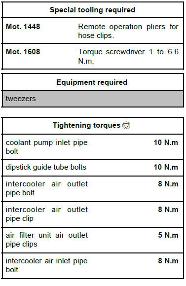
- Pivot the intercooler air inlet pipe clip (1) .
- Remove the intercooler air inlet pipe bolt (2) from the
fuel supply pipe bracket.
- Move aside the intercooler air inlet pipe
- Remove the engine undertray.
- Drain the cooling system .
- Remove:
- the air inlet sleeve clips
- the air inlet sleeve from the air filter unit
- the battery
- the battery tray
- the air filter box
- Loosen the air filter unit air outlet pipe clip on the turbocharger.
- Disconnect:
- the oil vapour rebreathing pipe from the oil separator,
- the air filter unit air outlet pipe from the turbocharger.
- Fit a blanking plug into the oil separator opening.
- Remove:
- the inlet manifold
- the exhaust gas recirculation rigid pipe between
the exhaust manifold and the exhaust gas recirculation
intercooler .
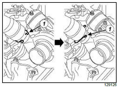
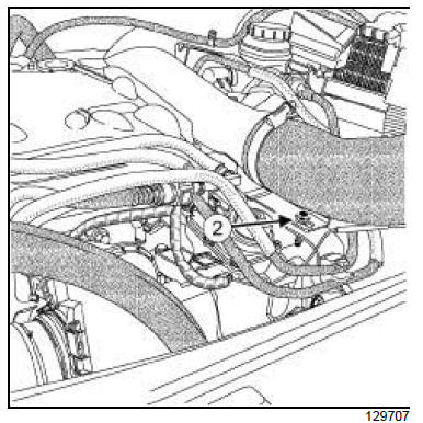
- Disconnect the connector (3) from the damper valve
wiring.
- Loosen the clip (4) on the intercooler air outlet pipe.
- Remove the intercooler air outlet pipe bolt (5) .
- Disconnect the intercooler air outlet pipe (6) from the
air inlet flap.
- Move the intercooler air outlet pipe to one side.
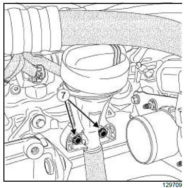
- Remove:
- the dipstick guide tube bolt (7) ,
- the dipstick tube.
- Fit a blanking plug on the opening of the dipstick
guide tube on the cylinder block.
- Remove the damper valve.
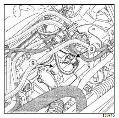
- Disconnect the turbocharger pressure sensor connector
(8) .
- Remove:
- the housing from the turbocharging pressure sensor
(9)
- the exhaust gas recirculation rigid pipe between
the exhaust gas recirculation solenoid valve and
the exhaust gas recirculation intercooler
- the starter
- the exhaust gas recirculation intercooler
- Unclip the wiring harness from the coolant pump inlet
pipe.
II - OPERATION FOR REMOVAL OF PART
CONCERNED
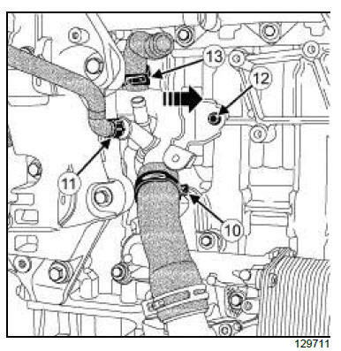
- Remove:
- the clip (10) from the coolant pump inlet pipe coming
from the oil filter unit using the tool (Mot. 1448).
- the clip (11) from the coolant pump inlet pipe coming
from the expansion bottle using the tool (Mot.1448).
- Remove the coolant pump inlet pipe bolt (12) .
- Pull the coolant pump inlet pipe in the direction of the
arrow.
- Move aside the coolant pump inlet pipe.
- Remove the clip (13) from the coolant pump inlet
pipe coming from the exhaust gas recirculation intercooler
using the tool (Mot. 1448).
- Disconnect:
- the hose coming from the exhaust gas recirculation
intercooler from the coolant pump inlet pipe,
- the hose coming from the oil filter unit from the
coolant pump inlet pipe,
- the hose coming from the expansion bottle from the
coolant pump inlet pipe.
- Remove the coolant pump inlet pipe.
REFITTING
I - REFITTING PREPARATION OPERATION
- Clean:
- the exhaust gas recirculation intercooler joint face,
- the exhaust gas recirculation solenoid valve joint
face,
| WARNING
The joint faces must be clean, dry and free from
grease (avoid finger marks). |
- Always replace:
- the coolant pump inlet pipe seal,
- the seal between the turbocharger pressure sensor
housing and the exhaust gas recirculation solenoid
valve
- the seal between the air inlet flap and the turbocharger
pressure sensor housing.
- Refit the new coolant pump inlet pipe seal.
II - REFITTING OPERATION FOR PART
CONCERNED
- Connect the hose coming from the exhaust gas recirculation
intercooler onto the coolant pump inlet
pipe.
- Refit the clip (13) on the coolant pump inlet pipe
coming from the exhaust gas recirculation intercooler
using the tool (Mot. 1448).
- Connect the coolant pump inlet pipe to the hose
coming from the oil filter unit.
| Note:
Check that the coolant pump inlet pipe is correctly
installed. The coolant may leak if it is incorrectly
installed. |
- Refit:
- the coolant pump inlet pipe,
- the coolant pump inlet pipe bolt.
- Torque tighten the coolant pump inlet pipe bolt
(10 N.m).
- Connect the hose coming from the expansion bottle
to the coolant pump inlet pipe.
- Refit:
- the clip on the coolant pump inlet pipe coming from
the oil filter unit using the tool (Mot. 1448),
- the clip on the coolant pump inlet pipe coming from
the expansion bottle using the tool (Mot. 1448).
III - FINAL OPERATION.
- Clip on the wiring of the coolant pump inlet pipe.
- Refit the exhaust gas recirculation intercooler.
- Refit:
- the starter
- the new exhaust gas recirculation rigid pipe seals
between the exhaust gas recirculation solenoid
valve and the exhaust gas recirculation intercooler
- the exhaust gas recirculation rigid pipe between
the exhaust gas recirculation solenoid valve and
the exhaust gas recirculation intercooler
- the new seal between the turbocharger pressure
sensor housing and the exhaust gas recirculation
solenoid valve
- the housing of the turbocharging pressure sensor.
- Connect the turbocharger pressure sensor connector.
- Refit:
- the new seal between the air inlet flap and the turbocharger
pressure sensor housing,
- the damper valve .
- Remove the blanking plug from the dipstick guide
tube on the cylinder block.
- Refit:
- dipstick guide ,
- the dipstick guide tube bolts.
- Torque tighten the dipstick guide tube bolts (10
N.m).
- Connect the intercooler air outlet pipe to the damper
valve.
- Refit the intercooler air outlet pipe bolt.
- Tighten:
- the intercooler air outlet pipe bolt (8 N.m),
- the intercooler air outlet pipe clip (8 N.m) using
the tool (Mot. 1608).
- Connect the damper valve wiring connector.
- Refit:
- the new exhaust gas recirculation rigid pipe seal on
the exhaust manifold
- the exhaust gas recirculation rigid pipe between
the exhaust manifold and the exhaust gas recirculation
intercooler
- the new inlet manifold seal
- the inlet manifold
- the inlet manifold hoses and pipes
- Refit the air filter unit.
- Connect the air filter unit air outlet pipe to the turbocharger
and the air filter unit.
- Torque tighten the air filter unit air outlet pipe
clips (5 N.m) using the tool (Mot. 1608).
- Remove the blanking plug from the opening of the oil
separator.
- Connect the oil vapour rebreathing pipe to the oil decanter.
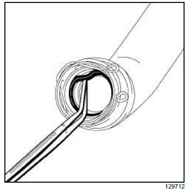
- Remove the intercooler air inlet pipe seal using the
tool tweezers.
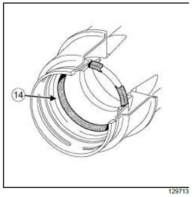
| Note:
Check that the seal (14) on the intercooler air
inlet pipe is fitted the correct way round. |
- Refit the new intercooler air inlet pipe seal.
- Rotate the intercooler air inlet pipe to refit the clip in
its housing.
- Clip the intercooler air inlet pipe onto the turbocharger.
- Refit the intercooler air inlet pipe bolt to the fuel supply
pipe bracket.
- Torque tighten the intercooler air inlet pipe bolt (8
N.m).
- Refit:
- the battery tray
- the battery
- the scoop under the scuttle panel grille
- the windscreen wiper mechanism
- the scuttle half-grille
- the windscreen wiper arms
- the air inlet sleeve to the air filter unit
- the air inlet sleeve clips.
- Fill the cooling system.
- Drain the cooling system.
- Refit:
- the engine cover,
- the engine undertray.
2TR
| IMPORTANT
To avoid all risk of damage to the systems, apply
the safety and cleanliness instructions and operation
recommendations before carrying out any
repair. |
| IMPORTANT
Wear protective gloves during the operation. |
REMOVAL
I - REMOVAL PREPARATION OPERATION
- Position the vehicle on a two-post lift.
| IMPORTANT
To prevent the vehicle from falling, lash it to the
vehicle lift using a strap. |
- Disconnect the battery.
- Remove the engine undertray.
- Drain the cooling system.
- Remove:
- the front right-hand wheel
- the front right-hand splash guard (
- the front right-hand wheel arch liner
- the accessories belt
- the fixed roller
- the auto tensioner
- the windscreen washer bottle filler neck
- the alternator
- the coolant pump.
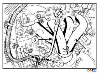
- Remove:
- the exhaust manifold upper heat shield bolts,
- the exhaust manifold upper heat shield,
- the clip (1) ,
- the dipstick guide tube bolt (2) ,
- the dipstick (3) and the dipstick guide tube,
- the exhaust manifold (4).
| Note:
The engine must remain covered to prevent
impurities from entering inside. |
II - OPERATION FOR REMOVAL OF PART
CONCERNED
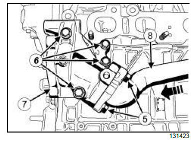
- Remove:
- the bolts (5) from the coolant pump inlet pipe,
- the coolant pump housing bolts (6) ,
- the coolant pump housing (7) ,
- the coolant pump housing seal,
- the coolant pump inlet pipe seal,
- the coolant pump inlet pipe (8) as shown on the diagram,
- the coolant pump inlet pipe O-ring at the thermostat.
REFITTING
I - REFITTING PREPARATION OPERATION
II - REFITTING OPERATION FOR PART
CONCERNED
- Refit:
- the coolant pump inlet pipe,
- the coolant pump inlet pipe seal,
- the coolant pump housing seal,
- the coolant pump housing,
- the coolant pump housing bolts,
- the coolant pump inlet pipe bolts.
- Torque tighten:
- the coolant pump housing bolts (22 N.m),
- the coolant pump inlet pipe bolts (22 N.m).
III - FINAL OPERATION.
- Refit:
- the exhaust manifold
- the dipstick and the dipstick guide tube
- the dipstick guide tube bolt.
- Torque tighten the dipstick guide tube bolt (22
Nm).
- Refit:
- the clip (1)
- the exhaust manifold upper heat shield
- the exhaust manifold upper heat shield bolts.
- Torque tighten the exhaust manifold upper heat
shield bolts (6 N.m).
- Refit:
- the coolant pump
- the alternator
- the windscreen washer bottle filler neck
- the auto tensioner
- the fixed roller
- the accessories belt
- the front right-hand wheel arch liner
- the front right-hand splash guard
- the front right-hand wheel
- Fill the cooling system .
- Refit the engine undertray.
- Connect the battery.
- Bleed the cooling system.
|


