2TR
| IMPORTANT
Wear protective gloves during the operation. |
REMOVAL
I - REMOVAL PREPARATION OPERATION
- Position the vehicle on a two-post lift.
| IMPORTANT
To prevent the vehicle from falling, lash it to the
vehicle lift using a strap. |
- Remove:
- the air intake sleeve
- the battery
- the battery tray
- the air filter unit
- the air resonator located on the rocker cover
- the air inlet duct
- the windscreen wiper arms
- the scuttle half-grille
- the windscreen wiper mechanism
- the scoop under the scuttle panel grille
- the motorised throttle valve without disconnecting
the cooling hoses
- the intake distributor
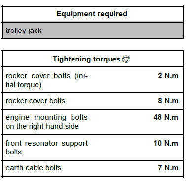
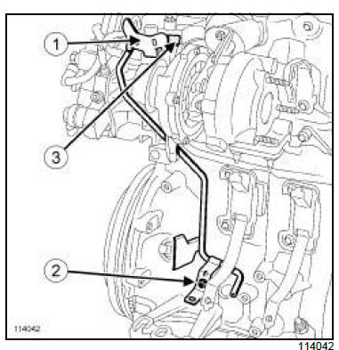
- Remove:
- the earth cable bolts (1) ,
- the wiring clip (2) .
- Disconnect the ignition coil connectors.
- Move aside the wiring (3) .
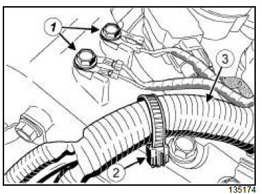
- Remove:
- the front resonator support bolts (4) ,
- the front resonator support (5) ,
- the pipes on the rocker cover,
- the engine undertray.
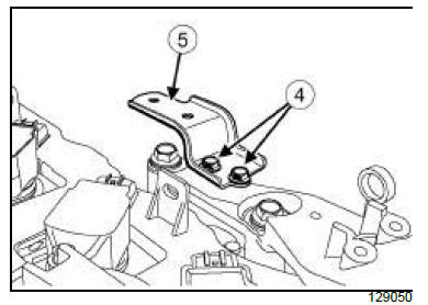
| Note:
To ensure stability, place a wooden block or
equivalent on the support surface. |
| Note:
To ensure stability, place an object behind the
trolley jack or equivalent to provide support. |
- Fit the trolley jack or an equivalent engine support
tool under the cylinder block.
- Remove the right-hand suspended engine mounting.
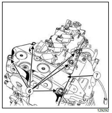
- Remove:
- the engine mounting bolts (6) on the right-hand
side,
- the engine mounting on the right-hand side (7) ,
- the ignition coils.
II - OPERATION FOR REMOVAL OF PART
CONCERNED
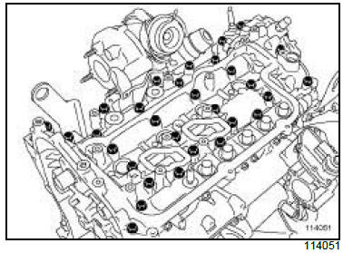
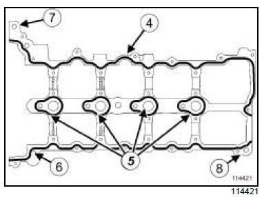
- Remove:
- the rocker cover bolts in order,
- the rocker cover,
- the rocker cover gasket.
REFITTING
I - REFITTING PREPARATION OPERATION
- Always replace the rocker cover seal.
| WARNING
The joint faces must be clean, dry and free from
grease (avoid finger marks). |
- Use SUPER CLEANER FOR JOINT FACES.
| WARNING
Applying excess sealant could cause it to be
squeezed out when parts are tightened. A mixture
of sealant and fluid could damage certain
components (engine, radiator, etc.). |
- Apply a beading (A) of SILICONE ADHESIVE
SEALANT.
II - REFITTING OPERATION FOR PART
CONCERNED
- Refit:
- the new seal on the rocker cover,
- the rocker cover.
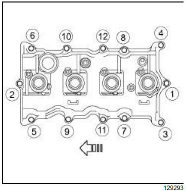
- Torque tighten in order:
- rocker cover bolts (initial torque) (2 N.m),
- rocker cover bolts (8 N.m).
III - FINAL OPERATION
- Refit:
- the ignition coils
- the engine mounting on the right-hand side
- the engine mounting bolts on the right-hand side.
- Torque tighten the engine mounting bolts on the
right-hand side (48 N.m).
- Refit the right-hand suspended engine mounting.
- Remove the trolley jack or equivalent engine supporting
tool from the cylinder block.
- Refit:
- the engine undertray,
- the pipes on the rocker cover,
- the front resonator support,
- the front resonator support bolts.
- Torque tighten the front resonator support bolts
(10 N.m).
- Connect the ignition coil connectors.
- Refit:
- the wiring clip,
- the earth cable bolts.
- Torque tighten the earth cable bolts (7 N.m).
- Refit:
- the inlet manifold
- the motorised throttle valve
- the scoop under the scuttle panel grille
- the windscreen wiper mechanism
- the scuttle half-grille
- the windscreen wiper arms
- the air inlet duct
- the air resonator located on the rocker cover
- the engine cover
- the air filter unit
- the battery tray
- the battery
- the air intake sleeve.
M9R
REMOVAL
I - REMOVAL PREPARATION OPERATION
- Remove the timing chain.
- Remove the exhaust gas pressure sensor.
- Remove:
- the vacuum pump
- the high pressure pipe between the pump and the
rail
- the oil decanter
- the diesel return rail
- the high pressure pipes between the rail and the injectors
- the diesel injectors .
- Remove the bolts (1) and (2) of the fuel collector outlet
pipe of the cylinder head.
- Disconnect the fuel collector outlet pipe from the cylinder
head at (3) .
- Move aside the fuel collector outlet pipe from the cylinder
head.
II - REMOVAL OF THE ROCKER COVER
- Remove the rocker cover bolts.
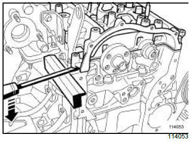
- Position a protective shim on the cylinder head.
- Detach the rocker cover using a flat-blade screwdriver,
using the shim for leverage.
- Remove the rocker cover - camshafts assembly.
REFITTING
I - REFITTING PREPARATION OPERATION
- Use SUPER CLEANING AGENT FOR JOINT FACES:
- the joint face on the rocker cover,
- the joint face on the cylinder head.
| WARNING
Do not scrape the joint faces of the aluminium,
any damage caused to the joint face will result in
a risk of leaks. |
| WARNING
Clean the cylinder head carefully to avoid any
foreign bodies entering the oil return and supply
pipes.
Failure to follow this advice could lead to the
blocking of the various oil inlet galleries, which
would quickly result in engine damage. |
- Remove the residue using a plastic spatula.
- Finish cleaning the joint faces using a GREY ABRASIVE
PAD.
- Use SURFACE CLEANER:
- the joint face on the rocker cover,
- the joint face on the cylinder head.
| WARNING
To ensure proper sealing, the gasket surfaces
must be clean, dry and not greasy (avoid any finger
marks). |
| WARNING
Applying excess sealant could cause it to be
squeezed out when parts are tightened. A mixture
of sealant and fluid could damage certain
components (engine, radiator, etc.). |
II - REFITTING THE ROCKER COVER
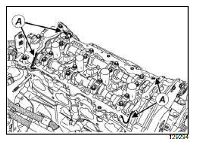
- Apply a bead of SILICONE ADHESIVE SEALANT with a diameter
of 1.5 +- 1 mm to the cylinder head at (4) , (5) , (6).
- Fit two studs (M6 - length 60 mm) into the holes (7)
and (8) on the cylinder head to guide the rocker cover.
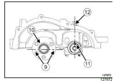
- Position:
- the groove on the exhaust side of the camshaft (9)
horizontally (large clearance (10) facing upwards),
- the groove on the inlet side of the camshaft (11)
facing towards the rocker cover boss (12) .
- Check that cylinders 1 and 4 are at Top Dead Centre
using the (Mot. 1766).
- Refit the rocker cover - camshafts assembly.
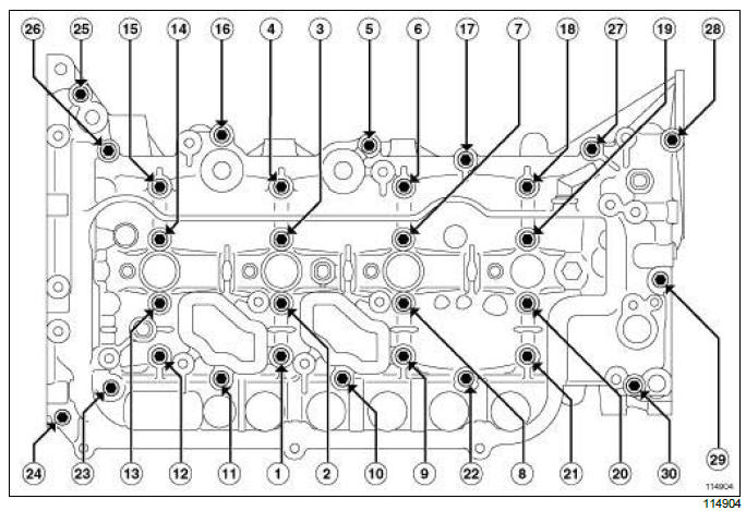
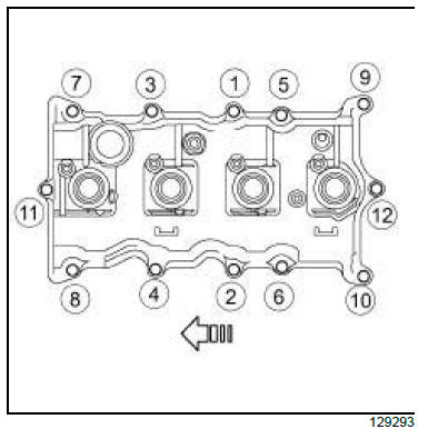
- Tighten in order and successively, the rocker cover
bolts (12), (15),(18) and (21) to gradually fit the rocker
cover on the cylinder head.
- Remove the two rocker cover guide studs.
- Fit without tightening the remaining rocker cover
bolts.
- Loosen bolts (12), (15), (18) and (21).
- Fit without tightening bolts (12), (15), (18) and (21).
- Tighten the rocker cover bolts in order.
- Clean the excess silicone adhesive sealant on the
timing and coupling faces using a plastic spatula.
III - FINAL OPERATION
- Connect the fuel collector outlet pipe of the cylinder
head.
- Tighten the bolts of the fuel collector outlet pipe of
the cylinder head.
- Refit:
- the diesel injectors
- the high pressure pipes between the rail and the injectors
- the diesel return rail
- the oil decanter
- the high pressure pipe between the pump and the
rail
- the vacuum pump
- Refit the exhaust gas pressure sensor.
- Refit the timing chain.
Camshaft dephaser:
Removal - Refitting
2TR
REMOVAL
I - REMOVAL PREPARATION OPERATION
- Remove the engine and gearbox assembly.
II - OPERATION FOR REMOVAL OF PART
CONCERNED
- Remove the camshaft dephaser.
REFITTING
I - REFITTING OPERATION FOR PART
CONCERNED NL
- Refit the camshaft dephaser.
II - FINAL OPERATION.
- Refit the engine and gearbox assembly.
|


