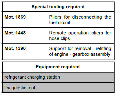
| IMPORTANT
To avoid all risk of damage to the systems, apply
the safety and cleanliness instructions and operation
recommendations before carrying out any
repair (see Engine: Precautions for the repair) . |
| IMPORTANT
Wear protective gloves during the operation. |
REMOVAL
I - OPERATION FOR REMOVAL OF PART
CONCERNED
- Position the vehicle on a two-post lift.
| IMPORTANT
To prevent the vehicle from falling, lash it to the
vehicle lift using a strap. |
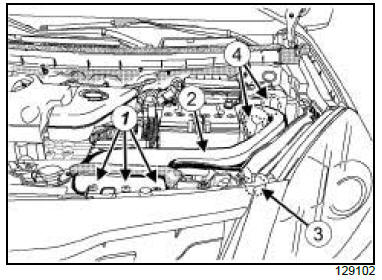
- To release the fuel pressure, remove:
- the air inlet sleeve clips (1) ,
- the air inlet sleeve (2) from the air resonator (3) and
the air filter unit (4) .
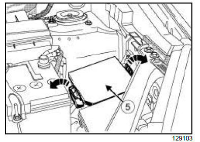
- Remove the cover (5) from the Protection and
Switching Unit.
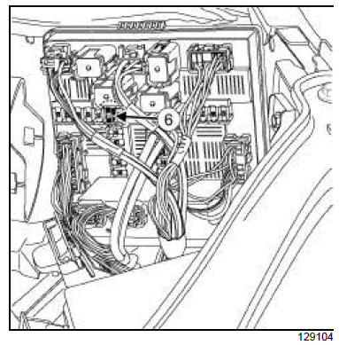
- Remove the fuse (6) of the fuel pump(F13) (15A).
- Release the fuel pressure of the fuel supply pipe.
| Note:
After switching the engine off, start it again two or
three times to fully release the fuel pressure. |
- Drain:
- the cooling system
- the manual gearbox oil
- the refrigerant circuit using a refrigerant charging
station
- Remove:
- the engine cover,
- the battery.
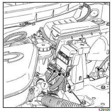
- Disconnect the battery positive terminal wiring connectors
(7) .
- Remove the battery tray.
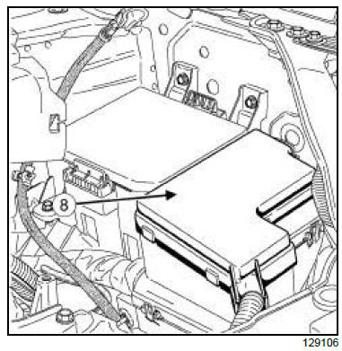
- Remove the engine fuse and relay box cover (8) .
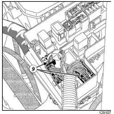
- Disconnect the engine fuse and relay box wiring
connectors (9) .
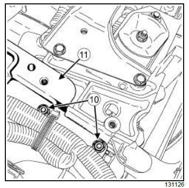
- Remove:
- the engine wiring support bolts (10) ,
- the engine wiring support (11) .
- the air filter box .
| Note:
Attach the engine wiring temporarily on the
engine side. |
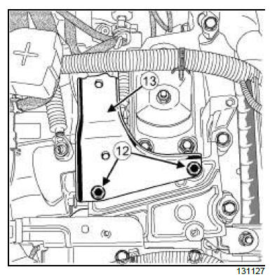
- Remove:
- the bolts (12) from the bracket,
- the bracket (13) ,
- the rocker cover air resonator.
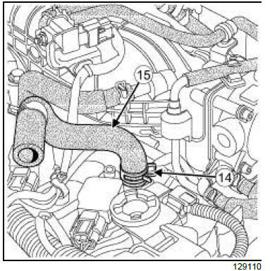
- Remove:
- the breather hose clip (14) ,
- the breather hose (15) ,
- the air inlet duct.
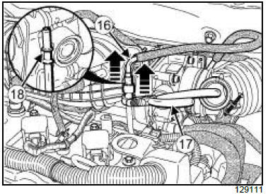
- Remove the plug of the fuel supply union.
| IMPORTANT During this operation, be sure to:
- refrain from smoking or bringing red hot objects
close to the working area,
- be careful of fuel splashes when disconnecting
the union.
|
- Disconnect the quick-release union (16) from the
fuel supply pipe using the tool (Mot. 1869) (17) .
| Note:
Insert the tool (Mot. 1869) on the second retainer
(18) . |
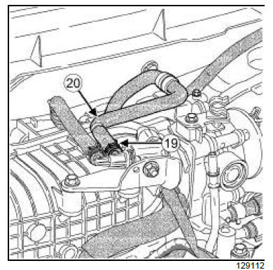
- Disconnect:
- the fuel vapour rebreathing hose clip (19) ,
- the fuel vapour rebreathing hose (20) .
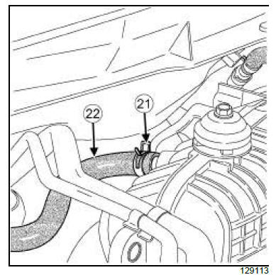
- Disconnect:
- the clip (21) from the brake servo vacuum pipe,
- the vacuum pipe (22) from the brake servo.
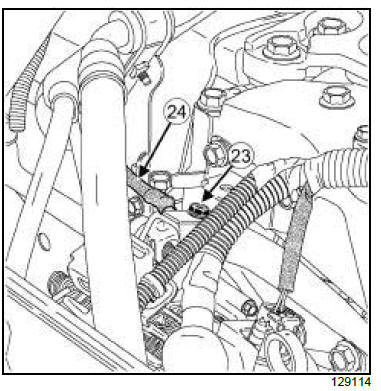
- Remove the alternator support earth cable bolt (23) .
- Disconnect the alternator support cable (24) .
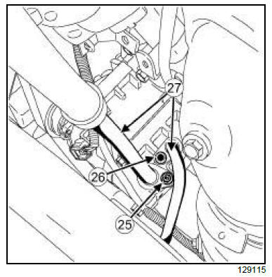
- Remove:
- the air conditioning pipe nut (25) ,
- the air conditioning pipe bolt (26) .
- Disconnect the air conditioning pipes (27) from the
air conditioning compressor.
- Fit plugs into the openings.
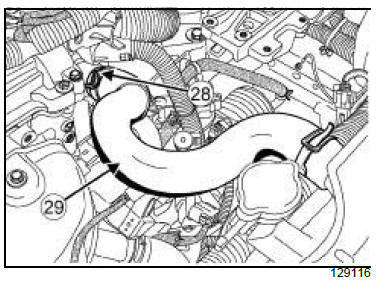
- Remove:
- the radiator upper hose clips (28) using the tool
(Mot. 1448)
- the radiator upper hose (29) .
| Note:
Take care with the remaining coolant. |
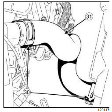
- Remove:
- the radiator lower hose clips (30) using the tool
(Mot. 1448),
- the radiator lower hose (31) .
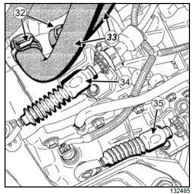
- Remove the clips (32) from the heater hoses.
- Disconnect:
- the heater hoses (33)
- the gear lever cable (34)
- the selector lever cable (35).
- Remove the front wheels.
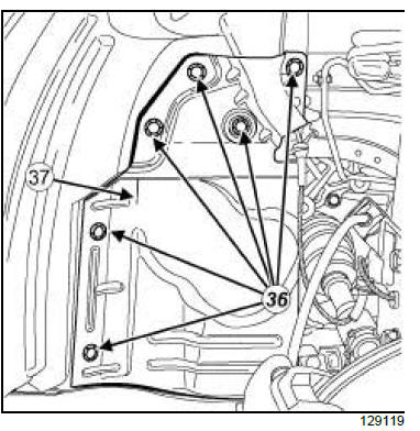
- Unclip the left-hand splash guard clips (36) .
- Remove the left-hand splash guard (37) .
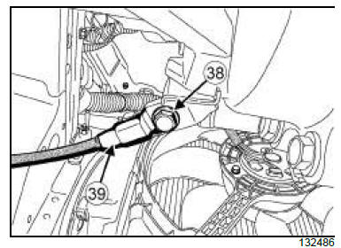
- Remove the manual gearbox earth cable bolt (38) .
- Disconnect the manual gearbox earth cable (39) .
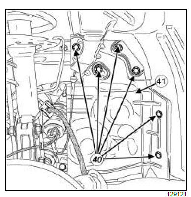
- Unclip the right-hand splash guard clips (40) .
- Remove:
- the right-hand splash guard (41) ,
- the connector pipe ,
- the front left-hand driveshaft ,
- the front right-hand driveshaft,
- the rear suspended engine mounting,
- the front axle subframe.
ND5
- Disconnect the longitudinal driveshaft from the
transfer box .
- Secure the longitudinal driveshaft to the control cable
bracket using a cord.
- Remove the transfer box.
II - OPERATION FOR REMOVAL OF PART
CONCERNED
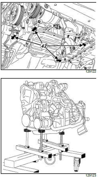
- Support the " engine-gearbox " assembly on the
(Mot. 1390) at (42) .
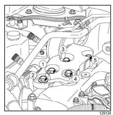
- Remove in order the right-hand suspended engine
mounting bolts.
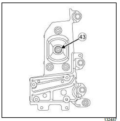
- Remove the left-hand suspended engine mounting
nut (43) from the gearbox.
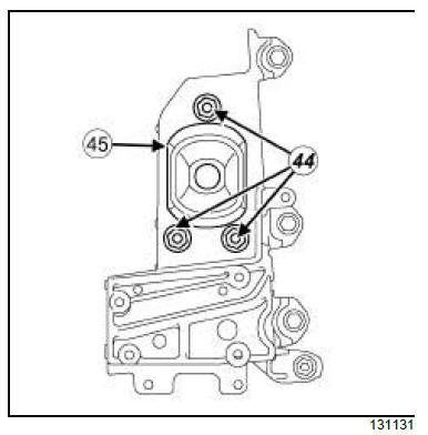
- Remove:
- the nuts (44) and bolts from the left-hand suspended
engine mounting,
- the rubber pad (45) from the left-hand suspended
engine mounting.
| Note:
Check that no part is interfering with the vehicle
side.
Before and during lifting, always check that the
wiring remains connected.
During removal, always take care to prevent the
vehicle from falling off the lift because of changes
in its centre of gravity. |
- Raise the lift to remove the " engine-gearbox " assembly.
REFITTING
I - REFITTING PREPARATION OPERATION
- For standard engine replacement.
- Always replace the O-rings on the air conditioning
pipes.
II - REFITTING OPERATION FOR PART
CONCERNED
| Note:
Never allow engine oil to come into contact with
the suspended engine mounting. Do not damage
the suspended engine mountings.
Check that every suspended engine mounting is
fitted correctly and tighten the nuts and bolts. |
- Fit the " engine - gearbox " assembly into the engine
compartment using the tool (Mot. 1390).
- Refit the rubber pad on the left-hand suspended engine
mounting.
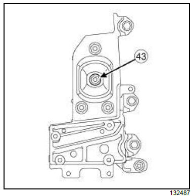
- Refit:
- the left-hand suspended engine mounting nut (43)
on the gearbox.
- the bolts and the nuts of the left-hand suspended
engine mounting.
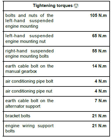
- Torque tighten:
- the bolts and nuts of the left-hand suspended
engine mounting (105 N.m),
- the left-hand suspended engine mounting nut
(65 N.m).
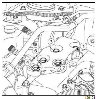
- Refit in order the right-hand suspended engine
mounting bolts.
- Torque tighten in order the right-hand suspended
engine mounting bolts (55 N.m).
III - FINAL OPERATION.
ND5
- Refit:
- the transfer box
- the longitudinal driveshaft on the transfer box
- Refit:
- the front right-hand driveshaft
- the front left-hand driveshaft
- the connector pipe
- the front axle subframe
- the rear suspended engine mounting
- the right-hand splash guard.
- Clip on the right-hand splash guard clips.
- Connect the earth cable on the manual gearbox.
- Refit the earth cable bolt on the manual gearbox.
- Torque tighten the earth cable bolt on the manual
gearbox (14 N.m).
- Refit the left-hand splash guard.
- Clip on the left-hand splash guard clips.
- Refit the front wheels.
- Connect:
- the selector lever cable
- the gear lever cable
- the heater hoses.
- Refit:
- the heater hose clips,
- the radiator lower hose,
- the radiator lower hose clips,
- the radiator upper hose,
- the radiator upper hose clips.
- Remove the caps from the apertures.
- Connect the air conditioning pipes on the air conditioning
compressor.
- Refit:
- the bolt from the air conditioning pipe,
- the air conditioning pipe nut.
- Torque tighten:
- the air conditioning pipe bolt (4 N.m).
- the air conditioning pipe nut (4 N.m).
- Connect the earth cable on the alternator support.
- Refit the earth cable bolt on the alternator support.
- Torque tighten the earth cable bolt on the alternator
support (7 N.m).
- Refit:
- brake servo vacuum pipe ,
- the clip on the brake servo vacuum pipe,
- the fuel vapour rebreathing hose.
- the fuel vapour rebreathing hose clip.
- Connect the quick-release union on the fuel supply
pipe.
| Note:
Check the connection of the quick-release union
by pulling on the part. |
- Refit:
- the plug of the fuel supply union,
- the air inlet duct,
- the breather hose,
- the breather hose clip,
- The air resonator on the rocker cover .
- the air filter unit ,
- the bracket (13) ,
- the bracket bolts.
- Torque tighten the bracket bolts (21 N.m).
- Refit:
- the engine wiring support,
- the engine wiring support bolts.
- Torque tighten the engine wiring support bolts (21
N.m).
- Connect the engine fuse and relay box wiring connectors.
- Refit:
- the engine fuse and relay box cover,
- the battery tray.
- Connect the battery positive terminal wiring connectors.
- Refit:
- the battery,
- the engine cover,
- the fuel pump fuse,
- the Protection and Switching Unit cover,
- the air inlet sleeve on the air filter unit and on the air
resonator.
- Clip on the air inlet sleeve clips.
- Refill:
- the refrigerant circuit using a refrigerant charging
station
- the manual gearbox oil
- the cooling system .
- Bleed the cooling system .
| Note:
When replacing the engine, carry out the programming
using the Diagnostic tool. |
|


