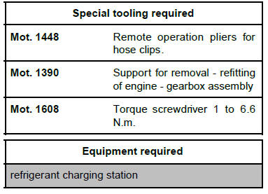
| IMPORTANT
Consult the safety and cleanliness advice and operation
recommendations before carrying out any
repair . |
REMOVAL
I - REMOVAL PREPARATION OPERATION
- Position the vehicle on a two-post lift .
- Remove:
- the engine cover,
- the air inlet sleeve clips,
- the air inlet sleeve from the air filter unit.
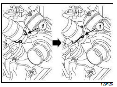
- Rotate the intercooler air inlet pipe clip (1) .
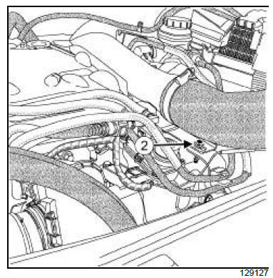
- Remove the intercooler air inlet pipe bolt (2) from the
fuel supply pipe bracket.
- Move the intercooler air inlet pipe to one side.
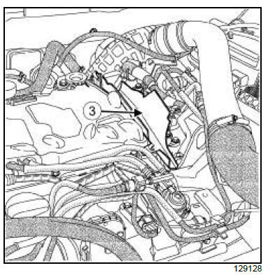
- Remove the protective plate (3) from the injector rail
protector.
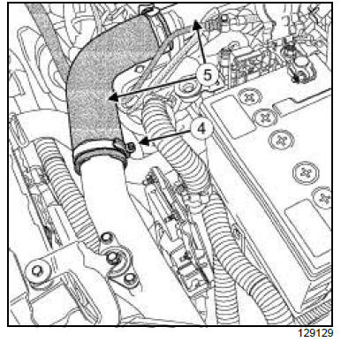
- Loosen the clip (4) on the intercooler air inlet pipe.
- Disconnect the " intercooler air inlet pipe - duct " assembly
(5) .
- Remove:
- the battery
- the battery tray
AIR CONDITIONING 01 or AIR CONDITIONING 02
- Drain the refrigerant circuit
- Remove the engine undertray.
- Drain the cooling system.
6-SPEED MANUAL GEARBOX
6-SPEED AUTOMATIC GEARBOX
- Drain the automatic transmission
AIR CONDITIONING 01 or AIR CONDITIONING 02
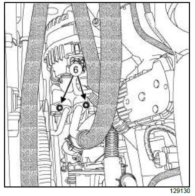
- Remove the compressor pipe union bolts (6) .
- Disconnect the compressor pipe unions.
- Plug the openings.
- Unclip the fuel pipes from their mounting support (7)
.
- Move the fuel pipes aside.
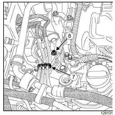
- Remove:
- the fuel pipe bolt (8) ,
- the fuel pipe support.
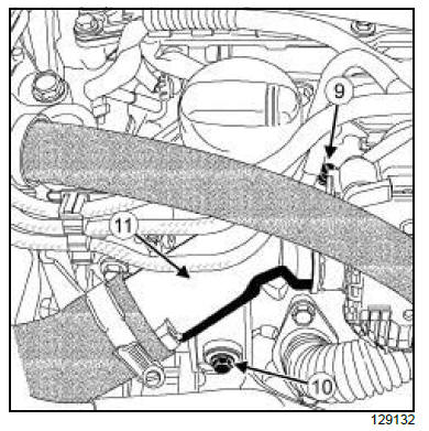
- Loosen the clip (9) on the intercooler air outlet pipe.
- Remove the intercooler air outlet pipe bolt (10) .
- Disconnect the intercooler air outlet pipe (11) from
the damper valve.
- Move the intercooler air outlet pipe to one side.
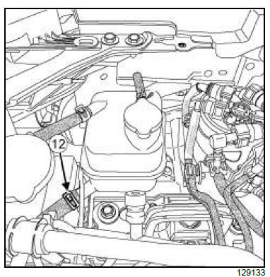
- Remove the clip (12) from the expansion bottle hose
using the tool (Mot. 1448).
- Disconnect the hose from the expansion bottle.
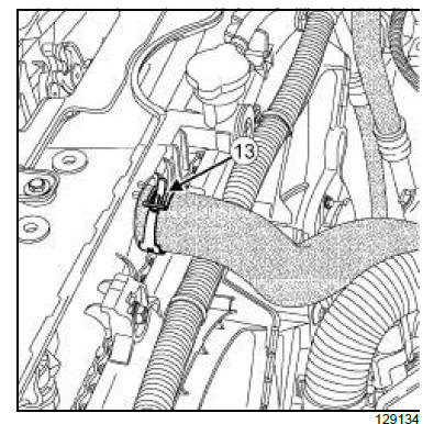
- Remove the cooling radiator top hose clip (13) using
the (Mot. 1448).
- Disconnect the cooling radiator top hose.
- Remove:
- the fuel filter
- the manual priming pump
- Disconnect the fuel return quick-release union leading
to the tank.
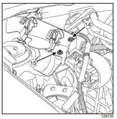
- Unclip the wiring (14) from the manual priming pump
support.
- Remove:
- the support bolt (15) of the manual priming pump,
- the manual priming pump support.
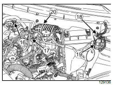
- Disconnect:
- the turbocharging pressure regulation valve actuating
hose (16) ,
- the brake servo hose (17) from the non-return
valve.
- Remove the bolt (18) from the turbocharging pressure
regulation actuating solenoid valve support.
- Move aside the turbocharging pressure regulation
actuating solenoid valve (19) and the turbocharging
pressure regulation valve actuating hoses (16) .
- Remove the air filter unit .
- Loosen the air filter unit air outlet pipe clip located on
the turbocharger side.
- Disconnect the air filter unit air outlet pipe (20) from
the turbocharger.
LEFT-HAND DRIVE
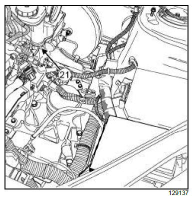
- Disconnect the brake fluid level sensor connector
(21) .
RIGHT-HAND DRIVE
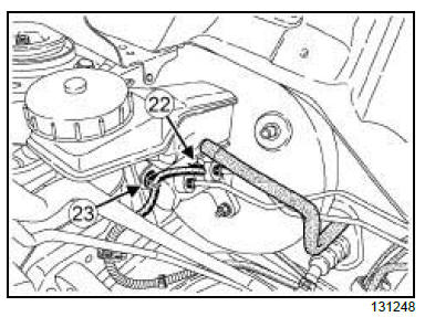
- Disconnect the brake fluid level sensor connector
(22) .
- Unclip the brake fluid level sensor wiring harness at
(23) .
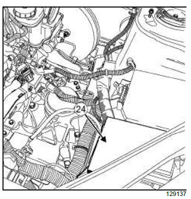
- Remove the fuse box cover (24) .
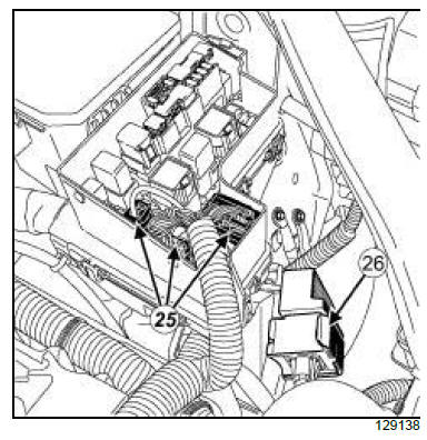
- Disconnect:
- the fuse box wiring connectors (25) ,
- the pre-postheating unit connector (26) .
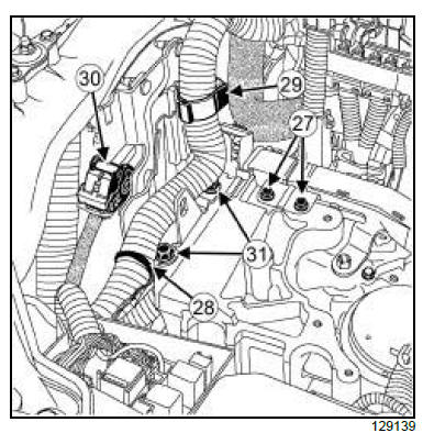
- Remove the bolts (27) from the wiring bracket.
- Unclip:
- the wiring at (28) ,
- the wiring at (29) .
6-SPEED AUTOMATIC GEARBOX
- Disconnect the connector (30) from the automatic
transmission computer.
- Remove:
- the automatic transmission computer mounting
bolts (31) ,
- the earth cable,
- the " automatic transmission computer - mounting
support " assembly.
6-SPEED MANUAL GEARBOX
- Remove the automatic transmission computer
mounting.
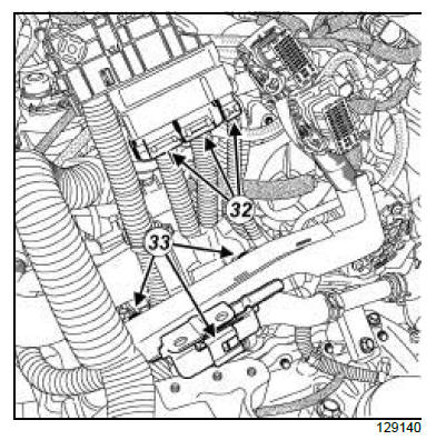
- Disconnect the battery protection fuse wiring connectors
(32) .
- Unclip the wiring harness from the brackets at (33) .
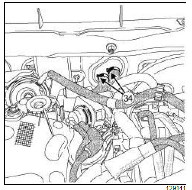
- Remove the heater matrix pipe clips (34) using the
(Mot. 1448).
- Disconnect the heater matrix pipes.
6-SPEED MANUAL GEARBOX
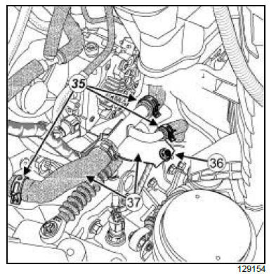
- Remove:
- the heater matrix coolant outlet pipe clips (35) using
the tool (Mot. 1448),
- the heater matrix water outlet pipe bolt (36) .
- Disconnect the " heater matrix coolant outlet duct -
pipe " assembly (37) from the inlet distributor and
the heater matrix coolant outlet pipe.
- Unclip:
- the selector cable and the gear selector lever cable
from the manual gearbox.
- the gear shift cable and the gear shift lever cable
from the manual gearbox.
6-SPEED AUTOMATIC GEARBOX
- Remove:
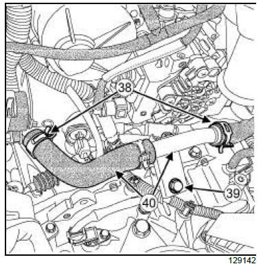
- the heater matrix coolant outlet pipe clips (38) using
the (Mot. 1448).
- the heater matrix coolant outlet pipe bolt (39) .
- Disconnect the " heater matrix coolant outlet pipe -
duct " assembly (40) from the inlet distributor and
the heater matrix coolant outlet pipe.
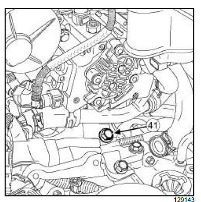
- Remove the heater matrix coolant inlet pipe bolt (41)
.
- Separate the coolant inlet hose from the heater matrix.
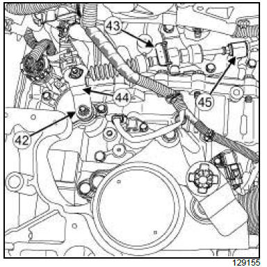
- Remove:
- the nut (42) of the automatic gearbox control cable,
- the stop (43) from the control cable of the automatic
gearbox.
- Unclip:
- the automatic gearbox control cable from the multifunction
switch lever (44) .
- the automatic gearbox control cable from the control
cable upper bracket (45) .
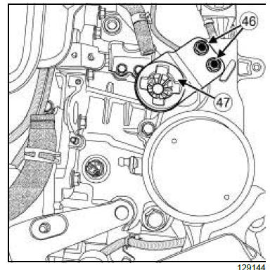
- Remove:
- the bolts (46) from the air filter unit support,
- the air filter unit support (47) .
6-SPEED MANUAL GEARBOX
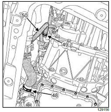
- Remove:
- the oil filter unit coolant inlet pipe clip (48) using the
(Mot. 1448),
- the clip (49) from the coolant hose using the tool
(Mot. 1448).
- Disconnect:
- the oil filter unit coolant inlet pipe,
- the coolant hose (50) .
6-SPEED AUTOMATIC GEARBOX
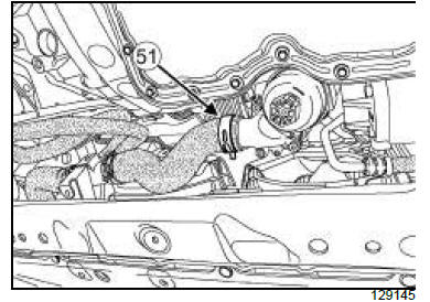
- Remove the oil filter unit coolant inlet pipe clip (51)
using the tool (Mot. 1448).
- Disconnect the oil filter unit coolant inlet pipe.
- Remove:
- the front wheels.
- the front splash guards.
- the front left-hand wheel driveshaft.
- the front right-hand wheel driveshaft.
- the electric coolant pump.
- the front axle subframe.
6-SPEED MANUAL GEARBOX
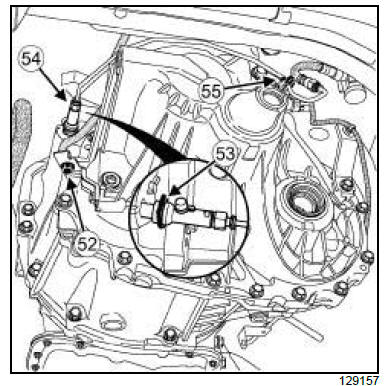
- Remove:
- the earth strap bolt (52) ,
- the earth strap,
- the clutch control pipe clip (53) .
- Disconnect the clutch control pipe (54) from the
manual gearbox.
- Unclip the clutch control pipe from its clip (55) .
- Drain the oil from the clutch control pipe.
6-SPEED AUTOMATIC GEARBOX
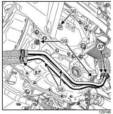
- Remove:
- the earth strap bolt (56) ,
- the earth strap.
- Remove the automatic gearbox coolant hose clips
(57) using the tool.
- Disconnect the automatic gearbox coolant hoses
from the automatic gearbox coolant pipe (58) .
- Remove:
- the automatic gearbox coolant pipe bolts (59) ,
- the automatic gearbox coolant pipe.
- Remove the particle filter.
4X4 TRANSMISSION
II - OPERATION FOR REMOVAL OF PART
CONCERNED
6-SPEED MANUAL GEARBOX
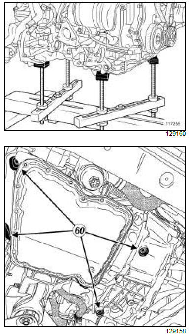
- Place the engine and the gearbox on the rubber
pads of the tool (Mot. 1390) at points (60) .
6-SPEED AUTOMATIC GEARBOX
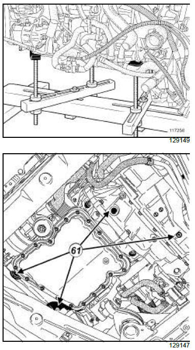
- Place the engine and the gearbox on the rubber
pads of the tool (Mot. 1390) at points (61) .
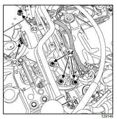
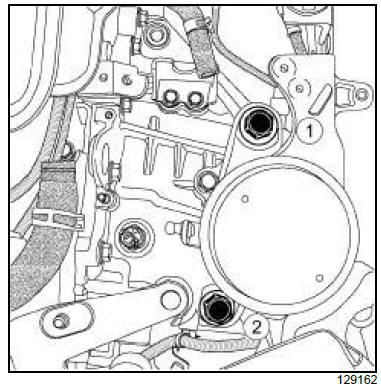
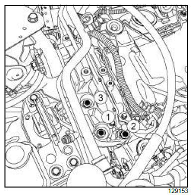
- Remove:
- the upper engine tie-bar bolt and washer (62) ,
- the upper engine tie-bar bolt (63) from the body,
- the upper engine tie-bar,
- the right-hand suspended engine mounting bolts
(64) .
6-SPEED MANUAL GEARBOX
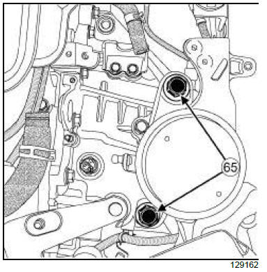
- Remove the left-hand suspended engine mounting
bolts (65) from the manual gearbox.
6-SPEED AUTOMATIC GEARBOX
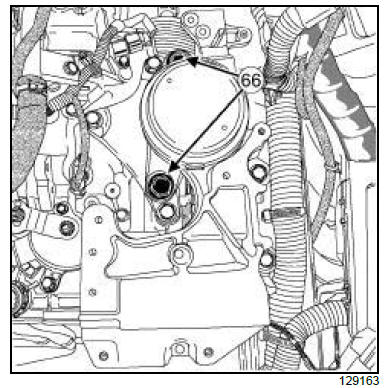
- Remove the left-hand suspended engine mounting
bolts (66) from the automatic gearbox.
- Remove the " engine - gearbox assembly " .
- Raise the vehicle.
- Move the " engine - gearbox assembly " aside.
REFITTING
I - REFITTING PREPARATION OPERATION
- Always replace:
- the intercooler air inlet pipe seal,
- the compressor pipe union seals,
- the engine tie-bar washer,
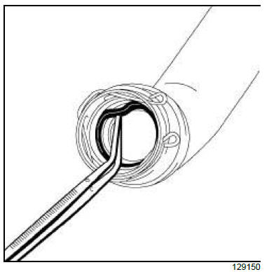
- Remove the intercooler air inlet pipe seal using a .
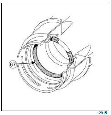
- Refit the new intercooler air inlet pipe seal (67) .
| Note:
Check that the seal on the intercooler air inlet
pipe is fitted the correct way round. |
II - REFITTING OPERATION FOR PART
CONCERNED
- Place the " engine-gearbox " assembly in the vehicle.
- Lower the vehicle.
6-SPEED MANUAL GEARBOX
- Refit the left-hand suspended engine bolts located
on the manual gearbox.
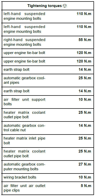
- Torque tighten in order the left-hand suspended
engine mounting bolts (110 N.m).
6-SPEED AUTOMATIC GEARBOX
- Refit the left-hand suspended engine bolts located
on the automatic gearbox.
- Torque tighten in order the left-hand suspended
engine mounting bolts (110 N.m) located on the
automatic gearbox.
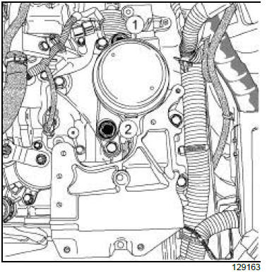
- Refit the right-hand suspended engine mounting
bolts located on the engine.
- Torque tighten in order the right-hand suspended
engine mounting bolts (55 N.m) located on the engine.
- Refit:
- the upper engine tie-bar,
- the upper engine tie-bar bolt on the body,
- the new upper engine tie-bar washer,
- the upper engine tie-bar bolt on the engine.
- Tighten to torque and in order:
- the upper engine tie-bar bolt (120 N.m) on the
engine,
- the upper engine tie-bar bolt (120 N.m) on the
body.
- Remove the tool (Mot. 1390).
III - FINAL OPERATION
4X4 TRANSMISSION
- Refit the particle filter.
6-SPEED MANUAL GEARBOX
- Clip the clutch control pipe onto its clip (55) .
- Connect the clutch control pipe onto the manual
gearbox.
- Refit
- the clutch control pipe clip (53)
- the earth strap,
- the earth strap bolt (52) .
- Torque tighten the earth strap bolt (14 N.m).
6-SPEED AUTOMATIC GEARBOX
- Refit:
- the automatic gearbox coolant pipe,
- the automatic gearbox coolant pipe bolts (59) .
- Torque tighten the automatic gearbox coolant
pipes (25 N.m).
- Connect the automatic gearbox coolant hoses onto
the automatic gearbox coolant pipes (58) .
- Refit the automatic gearbox coolant hose clips using
the (Mot. 1448).
- Refit:
- the earth strap,
- the earth strap bolt (56) .
- Torque tighten the earth strap bolt (14 N.m).
- Refit:
- the front axle subframe
- the electric coolant pump
- the front right-hand wheel driveshaft
- the front left-hand wheel driveshaft
- the front splash guards
- the front wheels
6-SPEED MANUAL GEARBOX
- Connect:
- the coolant hose (50) ,
- the oil filter unit coolant inlet pipe onto the oil filter
unit.
- Refit:
- the coolant hose clip (49) using the (Mot. 1448),
- the clip (48) on the oil filter unit coolant inlet pipe
using the (Mot. 1448).
6-SPEED AUTOMATIC GEARBOX
- Connect the oil filter unit coolant inlet pipe onto the
oil filter unit.
- Refit the clip (51) on the oil filter unit coolant inlet
pipe using the (Mot. 1448).
- Refit:
- the air filter unit support (47) ,
- the air filter unit mounting bolts (46) .
- Torque tighten the air filter unit support bolts (10
N.m).
6-SPEED MANUAL GEARBOX
- Clip on:
- the selector cable and the gear selector lever cable
from the manual gearbox
- the selector cable and the gear selector lever cable
from the manual gearbox
- Connect the " heater matrix coolant outlet pipe -
duct assembly " (37) onto the inlet distributor and
the heater matrix coolant outlet pipe.
- Refit the heater matrix coolant outlet pipe bolt (36) .
- Torque tighten the heater matrix coolant outlet
pipe bolt (25 N.m).
- Refit the heater matrix coolant outlet pipe clips (35)
using the (Mot. 1448).
6-SPEED AUTOMATIC GEARBOX
- Clip on:
- the automatic gearbox control cable onto the control
cable upper bracket,
- the automatic gearbox control cable onto the multifunction
switch lever.
- Refit:
- the automatic gearbox control cable nut,
- the automatic gearbox control cable stop.
- Torque tighten the automatic gearbox control cable
nut (14 N.m).
- Refit the heater matrix coolant inlet pipe bolt (41) .
- Torque tighten the heater matrix inlet pipe bolt (25
N.m).
- Connect the " heater matrix coolant outlet pipe -
duct " (40) assembly onto the inlet distributor and
the heater matrix coolant outlet hose.
- Refit the heater matrix coolant outlet pipe bolt (39) .
- Torque tighten the heater matrix coolant outlet
pipe bolt (25 N.m).
- Refit the heater matrix water outlet hose clips (38)
using the tool (Mot. 1448).
- Connect the heater matrix pipes.
- Refit the heater matrix pipe clips (34) using the (Mot.1448).
- Clip the wiring onto the brackets (33) .
- Connect the wiring connectors (32) to the battery
protection fuse.
6-SPEED MANUAL GEARBOX
- Refit the automatic gearbox computer mounting.
6-SPEED AUTOMATIC GEARBOX
- Fit:
- the " automatic gearbox computer - mounting
support " assembly,
- the earth cable.
- Refit the automatic gearbox computer mounting
bolts (31) .
- Torque tighten the automatic gearbox computer
mounting bolts (27 N.m).
- Connect the automatic gearbox computer connector.
- Clip on:
- the wiring at (30) ,
- the wiring at (29) .
- Refit the wiring bracket bolts (28) .
- Torque tighten the wiring bracket bolts (10 N.m).
- Connect:
- the pre-postheating unit connector (26) ,
- the wiring connectors (25) in the fuse box.
- Refit the fuse box cover.
LEFT-HAND DRIVE
- Connect the brake fluid level sensor connector (21) .
RIGHT-HAND DRIVE
- Clip on the brake fluid level sensor wiring at (23) .
- Connect the brake fluid level sensor connector (22) .
- Refit the air filter box.
- Connect the air filter unit air outlet pipe to the turbocharger
and the air filter unit.
- Torque tighten the air filter unit air outlet pipe
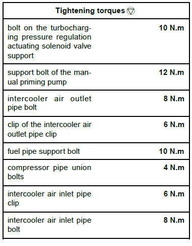
clips (5 N.m) using the tool (Mot. 1608).
- Place the turbocharging pressure regulation actuating
solenoid valve support on the air filter unit.
- Refit the bolt on the turbocharging pressure regulation
actuating solenoid valve support.
- Torque tighten the bolt on the turbocharging pressure
regulation actuating solenoid valve support
(10 N.m)
- Connect:
- the brake servo pipe to the non-return valve,
- the turbocharging pressure regulation valve actuating
hose (16) .
- Refit:
- the manual priming pump support,
- the support bolt of the manual priming pump.
- Torque tighten the support bolt of the manual
priming pump (12 N.m).
- Clip the wiring on the manual priming pump support
(14) .
- Connect the fuel return quick-release union of the
fuel pipe leading to the tank.
- Refit:
- the manual priming pump.
- the fuel filter.
- Connect the cooling radiator top hose.
- Refit the cooling radiator top hose clip using the tool
(Mot. 1448).
- Connect the expansion bottle hose.
- Refit the expansion bottle clip (12) using the (Mot.1448).
- Connect the intercooler air outlet pipe (11) to the
damper valve.
- Refit the intercooler air outlet pipe bolt (10) .
- Torque tighten:
- the intercooler air outlet pipe bolt (8 N.m),
- the clip of the intercooler air outlet pipe clip (6
N.m) using the tool (Mot. 1608).
- Refit the fuel pipe support.
- Refit the fuel pipe support bolt (8) .
- Torque tighten the fuel pipe support bolt (10 N.m).
- Clip the fuel pipes onto the fuel pipe support (7) .
AIR CONDITIONING 01 or AIR CONDITIONING 02
- Remove the blanking plugs from the compressor
and the compressor pipe unions.
- Refit the new compressor pipe union seals.
- Connect the compressor pipe unions onto the compressor.
- Refit the compressor pipe union bolts.
- Torque tighten the compressor pipe union bolts (4
N.m).
- Connect the " intercooler air inlet pipe-duct " assembly
(5) .
- Torque tighten the intercooler air inlet pipe clip (6
N.m) using the tool (Mot. 1608).
- Refit the protector plate on the injector rail protector.
- Rotate the intercooler air inlet pipe to refit the clip in
its housing.
- Clip the intercooler air inlet pipe onto the turbocharger.
- Refit the intercooler air inlet pipe bolt to the fuel supply
pipe bracket.
- Torque tighten the intercooler air inlet pipe bolt (8
N.m).
6-SPEED MANUAL GEARBOX
- Fill with oil:
- the manual gearbox .
- the brake fluid reservoir.
- Bleed the hydraulic clutch control .
6-SPEED AUTOMATIC GEARBOX
- Fill the automatic gearbox oil.
- Fill the cooling system.
- Bleed the cooling system.
- Refit the engine undertray.
AIR CONDITIONING 01 or AIR CONDITIONING 02
- Fill the refrigerant circuit using a refrigerant charging
station.
- Refit:
- the battery tray
- the battery
- the air inlet sleeve to the air filter unit
- the air inlet sleeve clips
- the engine cover.
|


