LEFT-HAND DRIVE
| IMPORTANT
Consult the safety and cleanliness advice and operation
recommendations before carrying out any
repair (see Steering: Precautions for the repair) . |
| IMPORTANT
To prevent the pyrotechnic components from being
permanently deactivated or triggered (airbags or
pretensioners), wait for at least 3 minutes after disconnecting
the battery. |
| IMPORTANT
Never handle the pyrotechnic systems (pretensioners
or airbags) near to a source of heat or naked
flame - they may be triggered. |
REMOVAL
I - REMOVAL PREPARATION OPERATION
- Unlock the steering column.
| IMPORTANT
To avoid any risk of triggering when working on
or near a pyrotechnic component (airbags or pretensioners),
lock the airbag computer using the
diagnostic tool.
When this function is activated, all the trigger
lines are inhibited and the airbag warning light on
the instrument panel lights up continuously (ignition
on). |
- Disconnect the battery.
- Set the wheels straight ahead.
- Remove:
- the driver's front airbag (see Driver's frontal airbag:
Removal - Refitting) (88C, Airbags and pretensioners),
- the steering wheel (see 36A, Steering assembly,
Steering wheel: Removal - Refitting, page 36A-
39) .
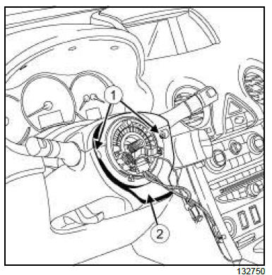
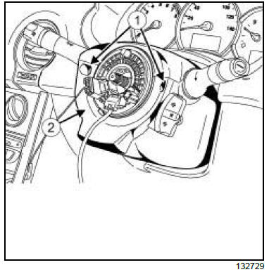
- Remove:
- the bolts (1) ,
- the half shell (2) ,
- the radio control satellite (see Radio control satellite:
Removal - Refitting) .
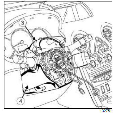
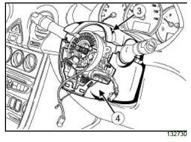
- Remove:
- the upper half shell (3) ,
- the lower half shell (4) ,
- the rotary switch (see Rotary switch: Removal -
Refitting) ,
- the steering column switch assembly (see Steering
column switch assembly: Removal - Refitting)
(84A, Control - Signals),
- the dashboard lower cover on the driver's side (see
Dashboard: Removal - Refitting) (57A, Interior
equipment),
- the front air distribution duct (see Front air distribution
duct: Removal - Refitting) .
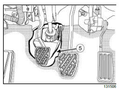
II - OPERATION FOR REMOVAL OF PART
CONCERNED
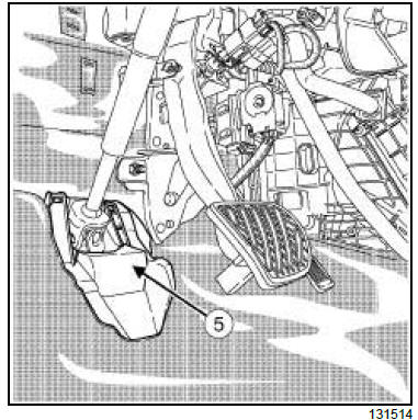
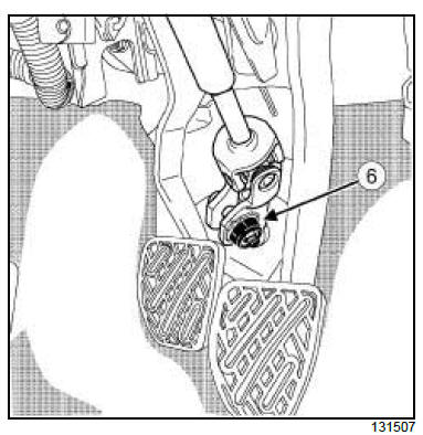
- Remove the steering cover (5) .
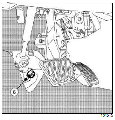
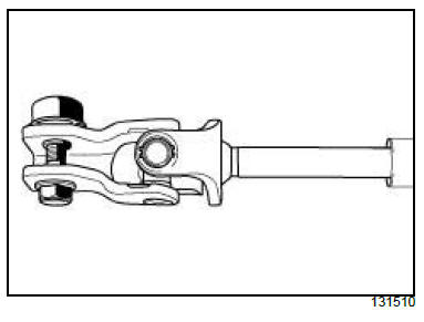
- Remove the cover (6) from the universal joint (do not
keep).
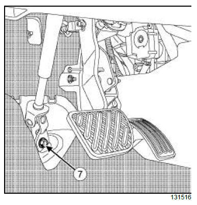
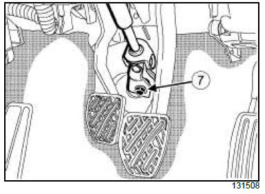
- Remove:
- the universal joint bolt (7) (do not keep),
- the universal joint nut (do not keep).
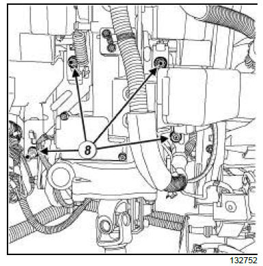
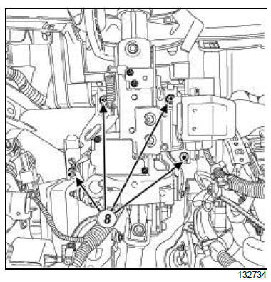
- Remove the steering column bolts and nuts (8) from
the cross member.
| Note:
The column cannot be set down directly on the
floor since the cable is not long enough. |
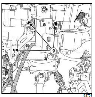
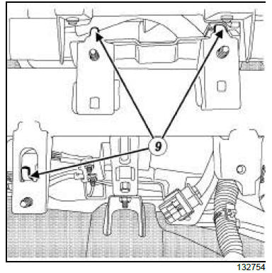
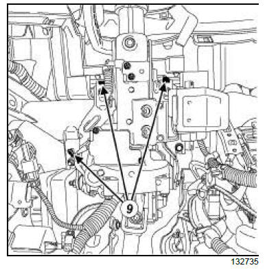
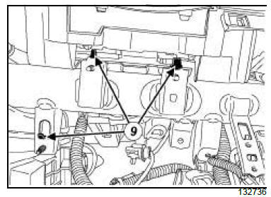
- Remove the steering column from the retainers (9).
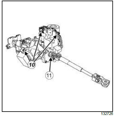
- Disconnect the connectors (10) .
- Remove:
- the steering column,
- the bolt (11) ,
- the intermediate shaft.
REFITTING
I - REFITTING PREPARATION OPERATION
- Always replace:
- the steering wheel nut,
- the steering wheel nut and bolt,
- the universal joint cam nut and bolt.
II - REFITTING OPERATION FOR PART
CONCERNED
- Refit:
- the intermediate shaft,
- the bolt.
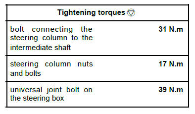
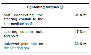
- Torque tighten the bolt connecting the steering
column to the intermediate shaft (31 N.m).
- Connect the connector.
- Refit:
- the steering column,
- the steering column bolts and nuts.
| Note:
Check that the steering column is held on the
cross member using the front and rear retainers
(9) before tightening it. |
- Torque tighten the steering column nuts and bolts
(17 N.m).
- Observe the direction of fitting for the universal joint
cam nut and bolt.
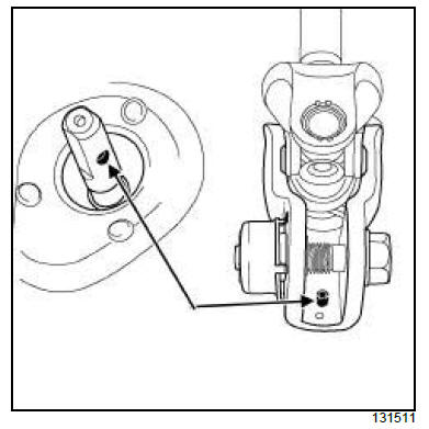
- Check that the universal joint is in the correct position.
- Fit the universal joint.
- Refit the universal joint new bolt and cam nut.
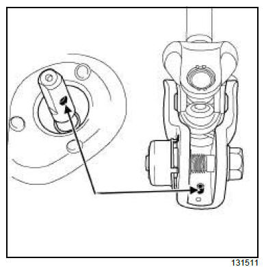
- Position the universal joint cam nut and bolt.
- Lock the cam nut in its housing (on the universal
joint).
- Pretighten the universal joint bolt.
- Tighten to torque the universal joint bolt on the
steering box (39 N.m).
III - FINAL OPERATION.
- Refit:
- the steering cover,
- the front air distribution duct (see Front air distribution
duct: Removal - Refitting) (61A, Heating
system).
- the dashboard lower cover on the driver's side (see
Dashboard: Removal - Refitting) (57A, Interior
equipment),
- the steering column switch assembly (see Steering
column switch assembly: Removal - Refitting)
(84A, Control - Signals),
- the rotary switch (see Rotary switch: Removal -
Refitting) (84A, Controls - Signals),
- the lower cover,
- the upper cover,
- the radio control satellite (see Radio control satellite:
Removal - Refitting) ,
- the half shell,
- the bolts,
- the steering wheel (see 36A, Steering assembly,
Steering wheel: Removal - Refitting, page 36A-
39) ,
- the driver's front airbag (see Driver's frontal airbag:
Removal - Refitting) (88C, Airbags and seat
belt pretensioners).
- Connect the battery (see Battery: Removal - Refitting)
(80A, Battery).
- Configure the steering wheel angle sensor (see
Fault finding - Configurations and programming
(38C, Anti-lock braking system).
RIGHT-HAND DRIVE
| IMPORTANT
Consult the safety and cleanliness advice and operation
recommendations before carrying out any
repair (see Steering: Precautions for the repair) . |
| IMPORTANT
To prevent the pyrotechnic components from being
permanently deactivated or triggered (airbags or
pretensioners), wait for at least 3 minutes after disconnecting
the battery. |
| IMPORTANT
Never handle the pyrotechnic systems (pretensioners
or airbags) near to a source of heat or naked
flame - they may be triggered. |
REMOVAL
I - REMOVAL PREPARATION OPERATION
- Unlock the steering column.
| IMPORTANT
To avoid any risk of triggering when working on
or near a pyrotechnic component (airbags or pretensioners),
lock the airbag computer using the
diagnostic tool.
When this function is activated, all the trigger
lines are inhibited and the airbag warning light on
the instrument panel lights up continuously (ignition
on). |
- Disconnect the battery (see Battery: Removal - Refitting)
(80A, Battery).
| Note:
If the airbag has been triggered, the steering column
must be replaced. |
- Set the wheels straight ahead.
- Remove:
- the driver's front airbag (see Driver's frontal airbag:
Removal - Refitting) (88C, Airbags and pretensioners),
- the steering wheel (see 36A, Steering assembly,
Steering wheel: Removal - Refitting, page 36A-
39) .
- Remove:
- the bolts (1) ,
- the half shell (2) ,
- the radio control satellite (see Radio control satellite:
Removal - Refitting) .
- Remove:
- the upper half shell,
- the upper half shell,
- the rotary switch (see Rotary switch: Removal -
Refitting) ,
- the steering column switch assembly (see Steering
column switch assembly: Removal - Refitting)
(84A, Control - Signals),
- the dashboard lower cover on the driver's side (see
Dashboard: Removal - Refitting) (57A, Interior
equipment),
- the front air distribution duct (see Front air distribution
duct: Removal - Refitting) .
II - OPERATION FOR REMOVAL OF PART
CONCERNED
- Remove the steering cover (5) .
- Remove the universal joint cover (6) (do not keep).
- Remove:
- the universal joint bolt (7) (do not keep),
- the universal joint nut (do not keep).
- Remove the steering column bolts and nuts (8) from
the cross member.
| Note:
The column cannot be set down directly on the
floor since the cable is not long enough. |
- Remove the steering column from the retainers (9) .
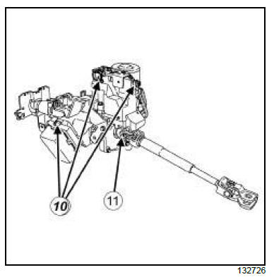
- Disconnect the connectors (10) .
- Remove:
- the steering column,
- the bolt (11) ,
- the intermediate shaft.
REFITTING
I - REFITTING PREPARATION OPERATION
- Always replace:
- the steering wheel nut,
- the steering column nut and bolt,
- the universal joint cam nut and bolt.
II - REFITTING OPERATION FOR PART
CONCERNED
- Refit:
- the intermediate shaft,
- the bolt.
- Torque tighten the bolt connecting the steering
column to the intermediate shaft (31 N.m).
- Connect the connectors.
- Refit:
- the steering column,
- the steering column nuts and bolts.
| Note:
Check that the steering column is held on the
cross member using the front and rear retainers
(9) before tightening it. |
- Torque tighten the steering column nuts and bolts
(17 N.m).
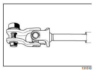
- Observe the direction of fitting for the universal joint
cam nut and bolt.
- Check that the universal joint is in the correct position.
- Fit the universal joint.
- Refit the universal joint new bolt and cam nut.
- Position the universal joint cam nut and bolt.
- Lock the cam nut in its housing (on the universal
joint).
- Pretighten the universal joint bolt.
- Tighten to torque the universal joint bolt on the
steering box (39 N.m).
III - FINAL OPERATION.
- Refit:
- the steering cover,
- the front air distribution duct (see Front air distribution
duct: Removal - Refitting) (61A, Heating
system).
- the dashboard lower cover on the driver's side (see
Dashboard: Removal - Refitting) (57A, Interior
equipment),
- the steering column switch assembly (see Steering
column switch assembly: Removal - Refitting)
(84A, Control - Signals),
- the rotary switch (see Rotary switch: Removal -
Refitting) (84A, Controls - Signals),
- the lower cover,
- the upper cover,
- the radio control satellite (see Radio control satellite:
Removal - Refitting) ,
- the half shell,
- the bolts,
- the steering wheel (see 36A, Steering assembly,
Steering wheel: Removal - Refitting, page 36A-
39) ,
- the driver's front airbag (see Driver's frontal airbag:
Removal - Refitting) (88C, Airbags and seat
belt pretensioners).
- Connect the battery (see Battery: Removal - Refitting)
(80A, Battery).
- Configure the steering wheel angle sensor (see
Fault finding - Configurations and programming
(38C, Anti-lock braking system).
|


