4X2 TRANSMISSION
REMOVAL
I - REMOVAL PREPARATION OPERATION
- Position the vehicle on a two-post lift (see Vehicle:
Towing and lifting) (02A, Lifting equipment).
- Release the parking brake.
- Remove:
- the rear wheels (see 35A, Wheels and tyres,
Wheel: Removal - Refitting, page 35A-1) ,
- the silencer (see Silencer: Removal - Refitting)
(19B, Exhaust).
- Fit the pedal press on the brake pedal to limit the
amount of brake fluid running out.
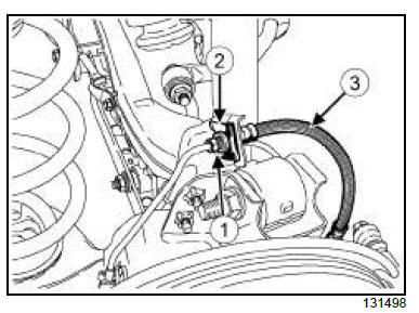
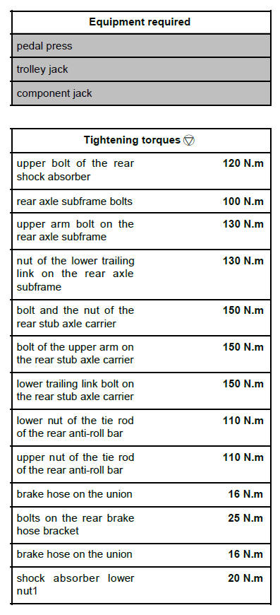
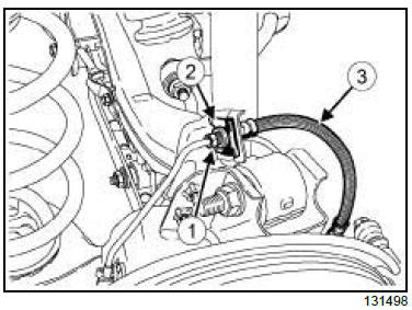
- Undo the rear brake hose at the pipe connection (1) .
- Remove the clip (2) from the rear brake hose (3) .
- Disconnect the rear brake hose.
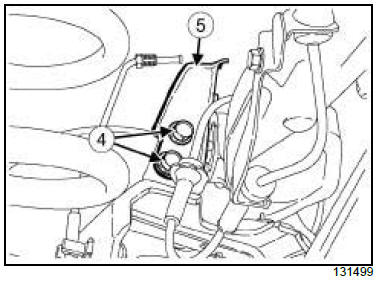
- Remove:
- the bolts (4) from the rear brake hose bracket,
- the rear brake hose bracket,
- the rear wheel speed sensor (see 38C, Anti-lock
braking system, Rear wheel speed sensor: Removal
- Refitting, page 38C-10) .
DISCHARGE LAMPS
- Remove the headlight beam adjustment rear sensor
(see Headlight beam adjustment rear sensor: Removal
- Refitting) (80C, Xenon bulbs).

- Undo the rear brake hose at the pipe connection (6) .
- Remove clip (7) .
- Disconnect the brake hose (8) .
- Remove the parking brake cables from the underbody
(see 37A, Mechanical component controls,
Parking brake cables: Removal - Refitting, page
37A-85) .
| Note:
It is not necessary to remove the parking brake
cables from the rear brake disc shield. |
II - OPERATION FOR REMOVAL OF PART
CONCERNED
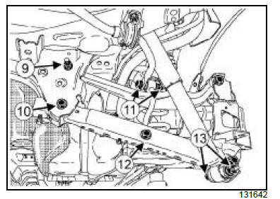
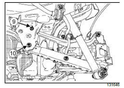
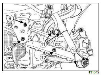
- Undo:
- the bolt and the nut (9) of the upper arm of the rear
axle subframe,
- the lower trailing link bolt and the nut (10) on the
rear axle subframe,
- the upper bolt and nut (11) of the tie rod of the rear
anti-roll bar,
- the lower bolt and nut (12) of the tie rod of the rear
anti-roll bar,
- the lower bolt and nut (13) of the rear shock absorber.
| WARNING
To prevent any damage, do not use the rear axle
as support for the lifting system. |
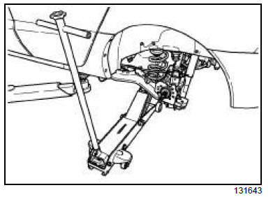
- Position the trolley jack with a shim under the lower
seat of the spring.
- Remove:
- the lower bolt and nut of the tie rod of the rear anti-roll
bar (12) ,
- the lower bolt and nut (13) of the rear shock absorber.
| Note:
Remove and refit one suspension spring, then
remove and refit the suspension spring on the
other side to avoid the springs being suddenly
released. |
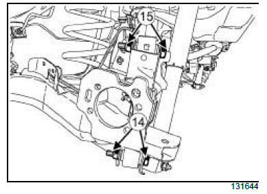
- Remove:
- the lower trailing link bolt and the nut (14) of the
rear stub axle carrier,
- the upper arm bolt and the nut (15) of the rear stub
axle carrier.
- Lower the trolley jack.
- Remove the rear suspension spring.
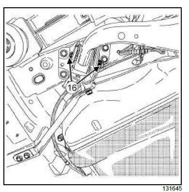
- Remove the bolt and the nut (16) from the rear stub
axle carrier.
- Position the component jack under the rear stub
axle carrier.
| Note:
This operation requires two people. |
- Remove:
- the "rear stub-axle carrier - rear brake disc shield -
rear brake lining - rear brake disc - rear brake calliper parking brake
cable" assembly,
- the "rear anti-roll bar - rear anti-roll bar tie rod" assembly.
- Remove:
- the lower trailing link bolt and the nut (10) from the
rear axle subframe,
- the lower trailing link,
- the bolt and the nut (9) of the upper arm of the rear
axle subframe,
- the upper arm.
- Position the component jack under the rear axle
subframe.
| Note:
This operation requires two people. |
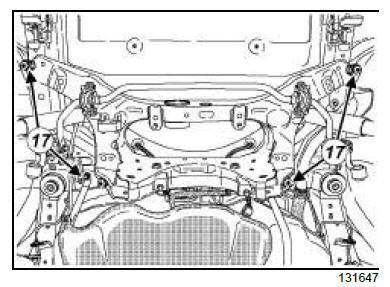
- Remove:
- the rear axle subframe bolts (17) ,
- the rear axle sub-frame with the rear shock absorber,
- the upper bolt and nut of the rear shock absorber,
- the rear shock absorber of the rear axle subframe.
REFITTING
I - REFITTING PREPARATION OPERATION
- Always replace:
- the upper arm nut,
- the lower trailing link nut,
- the lower nut of the tie rod of the rear anti-roll bar,
- the rear shock absorber nut,
- the rear stub axle carrier nut.
II - REFITTING OPERATION FOR PART
CONCERNED
| Note:
This operation requires two people. |
- Refit:
- the rear shock absorber on the rear axle subframe,
- the new upper bolt and nut of the rear shock absorber,
- the rear axle sub-frame with the rear shock absorber,
- the rear axle subframe bolts.
- Torque tighten:
- the upper bolt of the rear shock absorber (120
N.m),
- the rear axle subframe bolts (100 N.m).
- Refit:
- the rear anti-roll bar - rear anti-roll bar tie rod assembly,
- the upper arm,
- the new arm upper bolt and nut on the rear axle
subframe,
- the lower trailing link,
- the new lower trailing link bolt and nut on the rear
axle subframe.
| Note:
This operation requires two people. |
- Refit:
- the "rear stub-axle carrier - rear brake disc shield -
rear brake lining - rear brake disc - rear brake calliper
- parking brake cable" assembly,
- the new bolt and nut of the rear stub axle carrier.
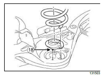
| Note:
The lower elastic bearing of the rear suspension
spring (18) must be firmly inserted into the opening
of the rear stub axle carrier. |
- Refit the rear suspension spring by aligning the lower
end of the widest section so it is positioned between
the lower elastic bearing and the rear stub
axle carrier.
- Position the trolley jack with a shim under the lower
seat of the spring.
| Note:
This operation requires two people. |
- Refit:
- the upper arm on to the rear stub-axle carrier,
- the new bolt and nut on to the upper arm,
- the lower trailing link of the rear stub-axle carrier,
- the new bolt and nut of the lower trailing link,
- the new lower bolt and nut of the rear shock absorber,
- the new lower bolt and nut of the tie rod of the rear
anti-roll bar.
- Lower the trolley jack.
| Note:
Tighten the lower nut of the shock absorber with
the wheels on the ground. |
- Torque tighten:
- The upper arm bolt on the rear axle subframe
(130 N.m),
- the nut of the lower trailing link on the rear axle
subframe (130 N.m)
- the bolt and the nut of the rear stub axle carrier
(150 N.m),
- the bolt of the upper arm on the rear stub axle
carrier (150 N.m),
- the lower trailing link bolt on the rear stub axle
carrier (150 N.m),
- the lower nut of the tie rod of the rear anti-roll
bar (110 N.m),
- the upper nut of the tie rod of the rear anti-roll
bar (110 N.m).
III - FINAL OPERATION.
- Refit the parking brake cables on to the underbody
(see 37A, Mechanical component controls, Parking
brake cables: Removal - Refitting, page 37A-
85) or (see 37A, Mechanical component controls,
Parking brake cables: Removal - Refitting, page
37A-85) .
DISCHARGE LAMPS
- Refit the headlight beam adjustment rear sensor
(see Headlight beam adjustment rear sensor: Removal
- Refitting) (80C, Xenon bulbs).
- Remove the brake hose.
- Refit:
- the brake hose on the union,
- the clip.
- Torque tighten the brake hose on the union (16
N.m).
- Refit:
- the rear wheel speed sensor (see 38C, Anti-lock
braking system, Rear wheel speed sensor: Removal
- Refitting, page 38C-10) ,
- the rear brake hose bracket,
- the bolts on the rear brake hose bracket,
- the rear brake hose,
- the brake hose on the union,
- the clip on the rear brake hose.
- Torque tighten:
- the bolts on the rear brake hose bracket (25
N.m),
- the brake hose on the union (16 N.m).
- Refit:
- the rear wheels (see 35A, Wheels and tyres,
Wheel: Removal - Refitting, page 35A-1) ,
- the silencer (see Silencer: Removal - Refitting)
(19B, Exhaust).
- Torque tighten the shock absorber lower nut1 (20
N.m).
DISCHARGE LAMPS
- Adjust:
- the headlights (see Headlight: Adjustment) (80B,
Headlights),
- the headlight beam adjustment rear sensor (see
Fault finding - Configuration and programming)
(80C, Xenon bulbs).
FOOT BRAKE AUTOMATIC CONTROL
- With the ignition on, push the handle to release the
electronic parking brake. Then pull the handle so
that the automatic parking brake locking function is
signalled by a sound and the play compensation is
set automatically.
FOOT BRAKE MANUAL CONTROL
- Adjust the parking brake cables (see 37A, Mechanical
component controls, Parking brake lever:
Removal - Refitting, page 37A-37) .
- Bleed the brake circuit (see 30A, General information,
Braking circuit: Bleed, page 30A-4) .
- Adjust:
- the alignment (see 30A, General information,
Rear axle system: Adjustment, page 30A-13) ,
- the neutral position of the steering wheel angle
sensor (see Fault finding - Configuration and
programming) (80B, Headlights).
4X4 TRANSMISSION
REMOVAL
I - REMOVAL PREPARATION OPERATION
- Position the vehicle on a two-post lift (see Vehicle:
Towing and lifting) (02A, Lifting equipment).
- Release the parking brake.
- Drain the rear final drive oil (see Rear axle oil:
Draining - Filling) (26A, Rear final drive).
- Remove:
- the rear wheels (see 35A, Wheels and tyres,
Wheel: Removal - Refitting, page 35A-1) ,
- the silencer (see Silencer: Removal - Refitting)
(19B, Exhaust).
- Uncouple the rear final drive propshaft (see Propshaft:
Removal - Refitting) (29A, Driveshafts).
- Secure the propshaft with string.
- Fit the pedal press on the brake pedal to limit the
amount of brake fluid running out.
- Undo the rear brake hose at the pipe connection (1) .
- Remove the clip (2) from the rear brake hose (3) .
- Disconnect the rear brake hose.
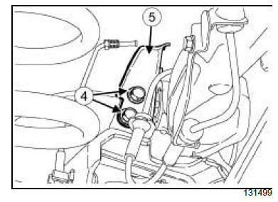
- Remove:
- the bolts (4) from the rear brake hose bracket,
- the rear brake hose bracket (5) ,
- the rear wheel speed sensor (see 38C, Anti-lock
braking system, Rear wheel speed sensor: Removal
- Refitting, page 38C-10) .
DISCHARGE LAMPS
- Remove the headlight beam adjustment rear sensor
(see Headlight beam adjustment rear sensor: Removal
- Refitting) (80C, Xenon bulbs).
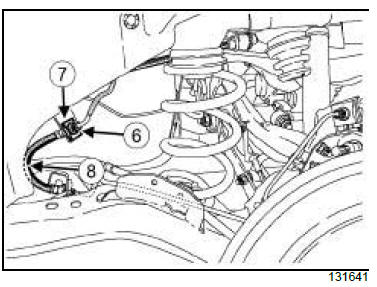
- Undo the rear brake hose at the pipe connection (6) .
- Remove clip (7) .
- Disconnect the brake hose (8) .
- Remove the parking brake cables from the underbody
(see 37A, Mechanical component controls,
Parking brake cables: Removal - Refitting, page
37A-85) .
| Note:
It is not necessary to remove the parking brake
cables from the rear brake disc shield. |
II - OPERATION FOR REMOVAL OF PART
CONCERNED
- Undo:
- the bolt and the nut (9) of the upper arm on the rear
axle subframe,
- the lower trailing link bolt and the nut (10) on the
rear axle subframe,
- the upper bolt and nut (11) of the tie rod of the rear
anti-roll bar,
- the lower bolt and nut (12) of the tie rod of the rear
anti-roll bar,
- the lower bolt and nut (13) of the rear shock absorber.
| WARNING
To prevent any damage, do not use the rear axle
as support for the lifting system. |
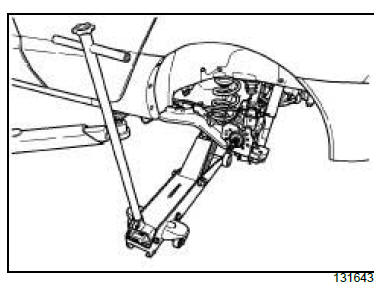
- Position the trolley jack with a shim under the lower
seat of the spring.
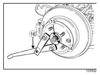
- Remove:
- the cotter pin (14) ,
- the wheel hub nut (15) using the tool (Rou. 604-01)
(16) .
- Remove:
- the lower bolt and nut (12) of the tie rod of the rear
anti-roll bar,
- the lower bolt and nut (13) of the rear shock absorber.
| Note:
Remove and refit one suspension spring, then
remove and refit the suspension spring on the
other side to avoid the springs being suddenly
released. |
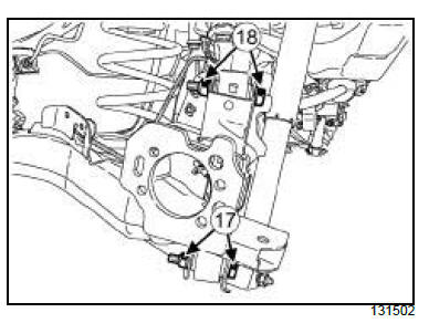
- Remove:
- the lower trailing link bolt and nut (17) of the rear
stub axle carrier,
- the upper arm bolt and nut (18) of the rear stub axle
carrier.
- Lower the trolley jack.
- Remove:
- the rear suspension spring,
- the rear driveshaft of the rear stub axle carrier.
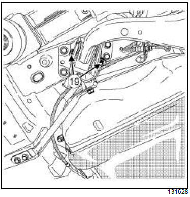
- Remove the bolt and nut (19) from the rear stub axle
carrier.
- Position the component jack under the rear stub
axle carrier.
| Note:
This operation requires two people. |
- Remove:
- the "rear stub-axle carrier - rear brake disc shield -
rear brake lining - rear brake disc - rear brake calliper
- parking brake cable" assembly,
- the rear final drive (see Rear final drive: Removal
- Refitting) ,
- the "rear anti-roll bar - rear anti-roll bar tie rod" assembly.
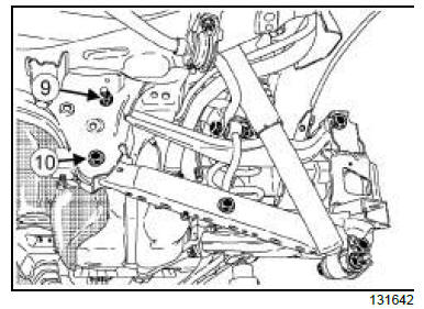
- Remove:
- the lower trailing link bolt and nut (10) from the rear
axle subframe,
- the lower trailing link,
- the bolt and nut (9) of the upper arm of the rear axle
subframe,
- the upper arm.
- Position the component jack under the rear axle
subframe.
| Note:
This operation requires two people. |
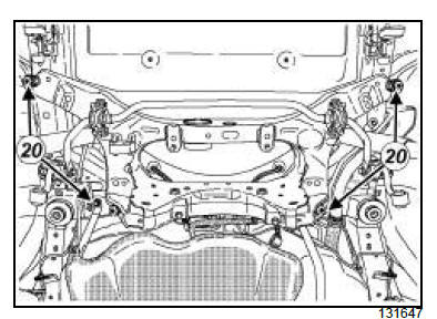
- Remove:
- the rear axle subframe bolts (20) ,
- the rear axle sub-frame with the rear shock absorber,
- the bolt and the upper nut of the rear shock absorber,
- the rear shock absorber of the rear axle subframe.
REFITTING
I - REFITTING PREPARATION OPERATION
- Always replace:
- the upper arm nut,
- the lower trailing link nut,
- the lower nut of the tie rod of the rear anti-roll bar,
- the rear shock absorber nut,
- the rear stub axle carrier nut,
- the cotter pin.
II - REFITTING OPERATION FOR PART
CONCERNED
| Note:
This operation requires two people. |
- Refit:
- the rear shock absorber on the rear axle subframe,
- the new upper bolt and nut of the rear shock absorber,
- the rear axle sub-frame with the rear shock absorber,
- the rear axle subframe bolts.
- Torque tighten:
- the upper bolt of the rear shock absorber (120
N.m),
- the rear axle subframe bolts (100 N.m).
- Refit:
- the rear anti-roll bar - rear anti-roll bar tie rod assembly,
- the rear final drive (see Rear final drive: Removal
- Refitting) (26A, Rear final drive),
- the upper arm,
- the new arm upper bolt and nut on the rear axle
subframe,
- the lower trailing link,
- the new lower trailing link bolt and nut on the rear
axle subframe.
| Note:
This operation requires two people. |
- Refit:
- the "rear stub-axle carrier - rear brake disc shield -
rear brake lining - rear brake disc - rear brake calliper
- parking brake cable" assembly,
- the new bolt and nut of the rear stub axle carrier.
- the rear driveshaft on to the rear stub axle carrier.
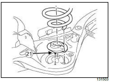
| Note:
The lower elastic bearing (21) of the rear suspension
spring must be firmly inserted into the opening
of the rear stub axle carrier. |
- Refit the rear suspension spring by aligning the lower
end of the widest section so it is positioned between
the lower elastic bearing and the rear stub
axle carrier.
- Position the trolley jack with a shim under the lower
seat of the spring.
| Note:
This operation requires two people. |
- Refit:
- the upper arm on to the rear stub-axle carrier,
- the new bolt and nut on to the upper arm,
- the lower trailing link of the rear stub-axle carrier,
- the new bolt and nut of the lower trailing link,
- the new lower bolt and nut of the rear shock absorber,
- the new lower bolt and nut of the tie rod of the rear
anti-roll bar.
- Lower the trolley jack.
| Note:
Tighten the lower nut of the shock absorber with
the wheels on the ground. |
- Torque tighten:
- The upper arm bolt on the rear axle subframe
(130 N.m),
- the nut of the lower trailing link on the rear axle
subframe (130 N.m)
- the bolt and nut of the rear stub axle carrier (150
N.m),
- the bolt of the upper arm on the rear stub axle
carrier (150 N.m),
- the lower trailing link bolt on the rear stub axle
carrier (150 N.m),
- the lower nut of the tie rod of the rear anti-roll
bar (110 N.m),
- the upper nut of the tie rod of the rear anti-roll
bar (110 N.m).
- Refit the wheel hub nut using the tool (Rou. 604-01).
- Torque tighten the wheel hub nut (125 N.m).
- Refit the new cotter pin.
III - FINAL OPERATION.
- Refit the parking brake cables on to the underbody
(see 37A, Mechanical component controls, Parking
brake cables: Removal - Refitting, page 37A-
85) .
DISCHARGE LAMPS
- Refit the headlight beam adjustment rear sensor
(see Headlight beam adjustment rear sensor: Removal
- Refitting) (80C, Xenon bulbs).
- Remove the brake hose.
- Refit:
- the brake hose on the union,
- the clip.
- Torque tighten the brake hose on the union (16
N.m).
- Refit:
- the rear wheel speed sensor (see 38C, Anti-lock
braking system, Rear wheel speed sensor: Removal
- Refitting, page 38C-10) ,
- the rear brake hose bracket,
- the bolts on the rear brake hose bracket,
- the rear brake hose,
- the brake hose on the union,
- the clip on the rear brake hose.
- Torque tighten:
- the bolts on the rear brake hose bracket (25
N.m),
- the brake hose on the union (16 N.m).
- Refit the rear wheels (see 35A, Wheels and tyres,
Wheel: Removal - Refitting, page 35A-1) .
- Torque tighten the shock absorber lower nut1 (20
N.m).
- Refit:
- the propshaft on the rear final drive (see Propshaft:
Removal - Refitting) (29A, Driveshafts),
- the silencer (see Silencer: Removal - Refitting)
(19B, Exhaust).
- Top up the rear final drive with oil (see Rear axle oil:
Draining - Filling) (26A, Rear final drive).
DISCHARGE LAMPS
- Adjust:
- the headlights (see Headlight: Adjustment) (80B,
Headlights),
- the headlight beam adjustment rear sensor(see
Fault finding - Configuration and programming)
(80C, Xenon bulbs).
FOOT BRAKE AUTOMATIC CONTROL
- With the ignition on, push the handle to release the
assisted parking brake. Then pull the handle so that
the automatic parking brake locking function is signalled
by a sound and the play compensation is set
automatically.
FOOT BRAKE MANUAL CONTROL
- Adjust the parking brake cables (see 37A, Mechanical
component controls, Parking brake lever:
Removal - Refitting, page 37A-37) .
- Bleed the brake circuit (see 30A, General information,
Braking circuit: Bleed, page 30A-4) .
- Adjust:
- the alignment (see 30A, General information,
Rear axle system: Adjustment, page 30A-13) ,
- the neutral position of the steering wheel angle
sensor (see Fault finding - Configuration and
programming) (80B, Headlights).
|


