2TR
| IMPORTANT
To avoid all risk of damage to the systems, apply
the safety and cleanliness instructions and operation
recommendations before carrying out any
repair. |
I - PREPARATION OPERATION FOR ADJUSTING
VALVE CLEARANCES
| IMPORTANT
To prevent the vehicle from falling, lash it to the
vehicle lift using a strap. |
| IMPORTANT
Wear protective gloves during the operation. |
- Position the vehicle on a two-post lift .
- Remove:
- the intake duct
- the battery
- the battery tray
- the air filter unit
- the engine cover
- The air resonator on the rocker cover
- the windscreen wiper arms
- the scuttle panel half-grille
- the windscreen wiper mechanism
- the scoop under the scuttle panel grille
- the inlet manifold
- the engine undertray.

- Place the trolley jack (1) or an equivalent engine
supporting tool under the cylinder block.
| Note:
Place a wooden block or equivalent on the support
surface to ensure stability. |
| IMPORTANT
To prevent any accidents, the trolley jack must
only be used to lift and/or move the vehicle. The
vehicle height must be maintained with axle
stands which are strong enough to support the
weight of the vehicle. |
- Remove the right-hand suspended engine mounting.
- Disconnect:
- the wiring on the right-hand engine mounting
bracket,
- the ignition coil connectors.
- Remove:
- the right-hand engine mounting bracket
- the ignition coils
- the rocker cover
- the front right-hand wheel
- the front right-hand wheel arch liner
II - VALVE CLEARANCE MEASUREMENT
OPERATION
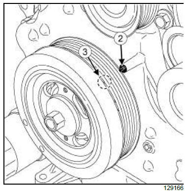
- Turn the crankshaft accessories pulley clockwise
and align the TDC mark (3) and the mark (2) located
on the timing cover.
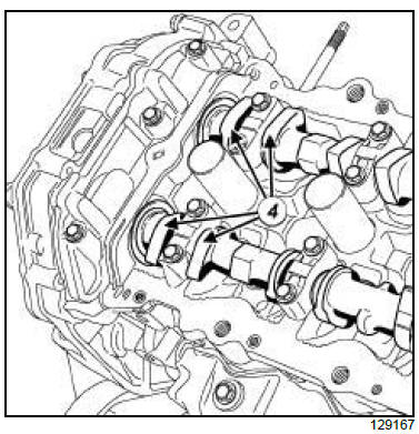
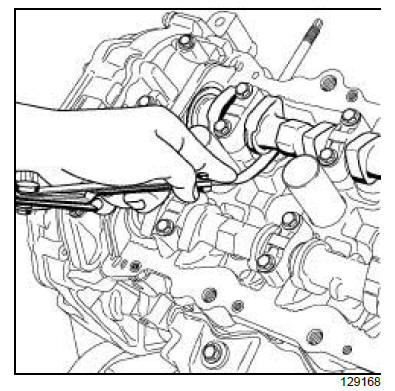
- Use a feeler gauge to measure the clearance between
the valve tappet and the camshaft.
| Note: Valve clearance:
- inlet:
0.24~0.32 mm (cold),
0.304~0.416 mm (hot: 80ºC).
- exhaust:
0.26~0.34 mm (cold),
0.308~0.432 mm (hot: 80ºC).
|
- Measurement positions (cylinder no. 1 at TDC):
- Cylinder no. 1: inlet and exhaust,
- Cylinder no. 2: inlet,
- Cylinder no. 3: exhaust.
- Measure the valve clearance in the locations indicated
by a black arrow on the diagram using a feeler
gauge.
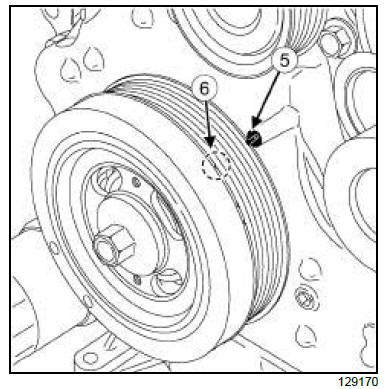
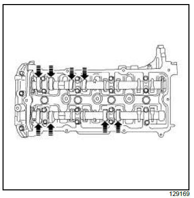
- Turn the crankshaft accessories pulley one turn
(360º) to align the TDC mark (6) and the mark (5) located
on the timing cover.
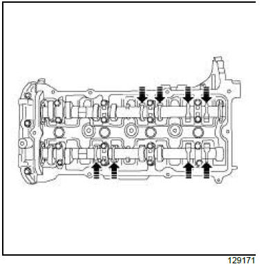
- Referring to the diagram, measure the valve clearance
in the locations indicated by a black arrow in
the diagram using a feeler gauge
- Measurement positions (cylinder no. 4 at TDC):
- Cylinder no. 2: exhaust,
- Cylinder no. 3: inlet,
- Cylinder no. 4: inlet and exhaust.
III - VALVE CLEARANCE ADJUSTMENT
OPERATION
- Engine and cylinder block assembly, Engine -
gearbox assembly: Removal - Refitting.
- Strip down the engine.
- Remove the timing - cylinder head.
- Adjust the valve clearance.
- Refit the timing - cylinder head.
- Rebuild the engine.
IV - FINAL OPERATION
- Refit:
- the front right-hand wheel arch liner
- the front right-hand wheel
- the rocker cover
- the ignition coils
- the right-hand engine mounting bracket.
- Connect:
- the ignition coil connectors,
- the wiring on the right-hand engine mounting
bracket.
- Refit the right-hand suspended engine mounting.
- Remove the trolley jack (1) or equivalent engine
support tool from under the cylinder block.
- Refit:
- the engine undertray
- the inlet manifold
- the scoop under the scuttle panel grille
- the windscreen wiper mechanism
- the scuttle panel half-grille
- the windscreen wiper arms
- The air resonator on the rocker cover
- the engine cover
- the air filter unit
- the battery tray
- the battery
- the inlet duct
|


