| IMPORTANT
To avoid all risk of damage to the systems, apply
the safety and cleanliness instructions and operation
recommendations before carrying out any
repair (see 62A, Air conditioning, Air conditioning:
Precautions for repair, page 62A-1) . |
Fault finding for detecting leaks:
| Component |
Detection area |
Part to be replaced after
first check |
Part to be replaced after
filling and second check |
| Condenser |
Inlet or outlet |
Pipe |
Condenser |
| Evaporator |
Connection flange |
Pipe |
Connection flange and/or
evaporator |
| Compressor |
Inlet or outlet |
Pipes |
Compressor |
I - ELECTRONIC DETECTORS
| Note:
Check for leaks using the electronic detector first
before using the trace detector. |
- This device measures variations in the quantity of
refrigerant in the air and beeps accordingly.
- The device must be initialised before checking.
To do this:
- immobilise the device,
- calibrate the device in the engine compartment,
- do not start the engine.
- This point is then used as standard for detecting the
contamination rate.
This device is highly sensitive: during the detection
process, only follow the line of the circuit as closely
as possible to limit variations caused by other gases.
This device only detects relatively substantial leaks.
| Note:
Make sure that the sensor at the end of the rod is
extremely clean and in good condition. |
II - TRACE DETECTORS
| WARNING
After injecting dye into the refrigerant, be sure to
indicate this on a label (supplied with the dye
capsule), and the date of the operation.
Position the label so it is visible near to the cold
loop filler valve. |
- Detecting leaks using a tracer involves adding a dye
to the refrigerant, and locating the points of loss
using an ultraviolet light.
| Note:
The procedure described must be observed. |
| Note:
Use this leak detection method as a last resort
for leaks that cannot be located. |
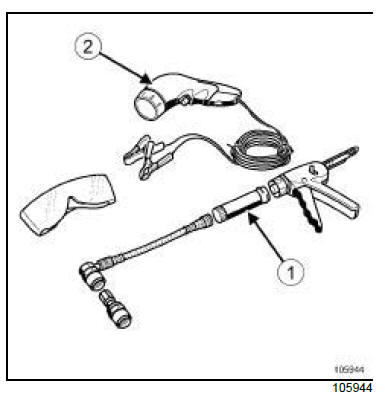
- The procedure for detecting refrigerant leaks uses a
dye which is available as a single-use capsule (1) :
traces of fluid are detected using an ultraviolet lamp
(2) .
- The dye remains in the air conditioning system.
- It is possible to check the status of the cold loop
using the ultraviolet lamp, without injecting the dye
again.
| WARNING
To avoid damaging the cold loop components
(corrosions, etc.), do not use dye if the traces
reveal that some product has already been injected. |
- If there is nothing to indicate that dye has been used
previously (label, etc.):
- position a cloth,
- release a small jet of refrigerant through the two
valves,
- light up the valve interior using the ultraviolet lamp,
- check for fluorescent traces.
- Add a dose of detection dye if there are no fluorescent
traces or label.
- Affix a label.
- Record the date when the dye was added.
1 - Injecting dye into the circuit
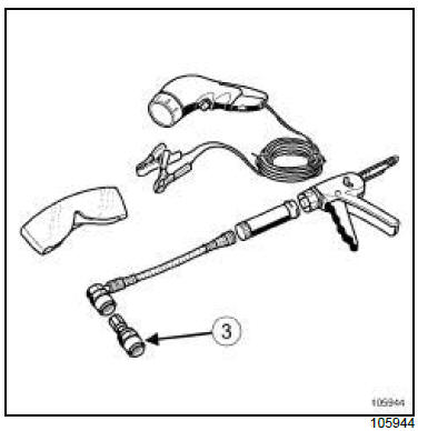
- For vehicles with a single valve, set up the dye injection
system on the low pressure valve by following
the circulation direction of the product and using the
union (3) .
- Inject the dye into the circuit.
- Run the air conditioning system for approximately 15
minutes.
2 - Leak detection procedure
- Carry out an initial check (with the engine stopped)
by sweeping the circuit with an ultraviolet light.
| Note:
Use an adjustable mirror wherever access is difficult. |
- If no leak is apparent:
- carefully clean the coolant circuit on the outside,
- run the air conditioning system until the leak is detected
(failing this, check the condition of the evaporator).
| WARNING
After injecting dye into the refrigerant, be sure to
indicate this on a label (supplied with the dye
capsule), and the date of the operation.
Position the label so it is visible near to the cold
loop filler valve. |
|


