Renault Koleos Service Repair Manual: Centre floor, side section: General description
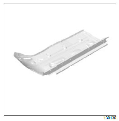
I - DESIGN OF THE STRUCTURAL COMPONENT
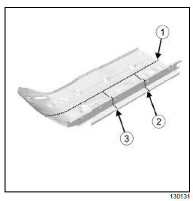
The component is made of two different kinds of panel of different thickness assembled by laser butt welding. II - AREA TO BE CUT FOR PARTIAL REPLACEMENT
These cutting lines show the area in which it is possible to carry out a partial replacement of the centre floor side section. Cut 1, 2 and 3:
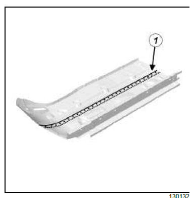
III - ASSEMBLY METHOD FOR A PARTIAL REPLACEMENT Only the connections which are specific to the partial replacement by cutting are indicated.
If there are other issues regarding access to mating faces, the various replacement options are described in the basic instructions for structural bodywork repair (see MR 400, 40A, General Information).
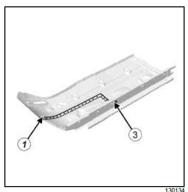
Line (1) on the diagram shows partial replacement and a weld by joggling with plug welds at regular intervals.
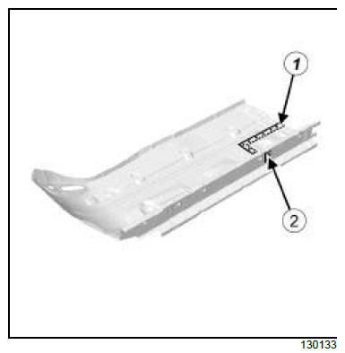
Lines (1) and (2) on the diagram show the partial rear replacement and a weld by joggling with plug welds at regular intervals.
Lines (1) and (3) on the diagram show the partial front replacement and a weld by joggling with plug welds at regular intervals. |


See More:
Renault Koleos Owners Manual > Starting, stopping the engine: Vehicle with key
Starting the engine Petrol versions Activate the starter without accelerating; release the key as soon as the engine starts. Never start your vehicle while freewheeling on a gradient. Risk of non-activation of power-assisted steering. There is a risk of accidents. Diesel versions Turn the ignition ...
Renault Koleos Owners Manual
- Getting to know your vehicle
- Driving
- Your comfort
- Maintenance
- Practical advice
- Technical specifications
Renault Koleos Service Repair Manual
